HP Sprout Pro G2 Maintenance & Service Guide - Page 71
Antennas, Disconnect the antennas from the WLAN module
 |
View all HP Sprout Pro G2 manuals
Add to My Manuals
Save this manual to your list of manuals |
Page 71 highlights
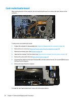
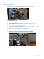
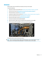
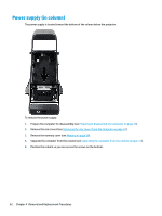
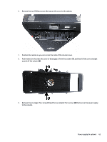
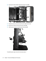
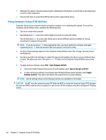
Antennas Antenna cables route from the WLAN card to antennas at the top of the computer. To remove the antennas: 1. Prepare the computer for disassembly (see Preparing to disassemble the computer on page 23). 2. Remove the rear covers (see Removing the rear covers from the computer on page 24). 3. Remove the memory cover (see Memory on page 29). 4. Separate the computer from the column (see Separating the computer from the column on page 41). 5. Remove the system board cover (see System board cover on page 43). 6. Remove the outer plastic trim (see System board cover on page 43). 7. Disconnect the antennas from the WLAN module (1). 8. Remove the antenna cables from the routing path and the clips built into the frame (2). 9. Peel the antennas off the frame (3). The antennas are secured using adhesive. To install the antenna, reverse the removal procedures. NOTE: When connecting the antennas cables to the WLAN module, connect the cable labeled "1" to the MAIN connector on the module and the cable labeled "2" to the AUX connector on the module. Antennas 61
-
 1
1 -
2
-
3
-
4
-
5
-
6
-
7
-
8
-
9
-
10
-
11
-
12
-
13
-
14
-
15
-
16
-
17
-
18
-
19
-
20
-
21
-
22
-
23
-
24
-
25
-
26
-
27
-
28
-
29
-
30
-
31
-
32
-
33
-
34
-
35
-
36
-
37
-
38
-
39
-
40
-
41
-
42
-
43
-
44
-
45
-
46
-
47
-
48
-
49
-
50
-
51
-
52
-
53
-
54
-
55
-
56
-
57
-
58
-
59
-
60
-
61
-
62
-
63
-
64
-
65
-
 66
66 -
 67
67 -
 68
68 -
 69
69 -
 70
70 -
 71
71 -
 72
72 -
 73
73 -
 74
74 -
 75
75 -
 76
76 -
77
-
78
-
79
-
80
-
81
-
82
-
83
-
84
-
85
-
86
-
87
-
88
-
89
-
90
-
91
-
92
-
93
-
94
-
95
-
96
-
97
-
98
-
99
-
100
-
101
-
102
-
103
-
104
-
105
-
106
-
107
-
108
-
109
-
110
-
111
-
112
-
113
-
114
-
115
-
116
-
117
-
118
-
119
-
120
-
121
-
122
-
123
-
124
-
125
-
126
-
127
-
128
-
129
-
130
-
131
-
132
-
133
-
134
-
135
-
136
 |
 |