Netgear GSM7212P GSM5212P/GSM7212P/GSM7212F/GSM7224P User Manual - Page 375
Configuration, CST Port Configuration, APPLY
 |
View all Netgear GSM7212P manuals
Add to My Manuals
Save this manual to your list of manuals |
Page 375 highlights
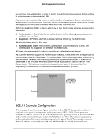
Web Management User Guide Ports 1/0/1 - 1/0/5 Connected to Hosts Ports 1/0/1 - 1/0/5 Connected to Hosts Ports 1/0/6 - 1/0/8 Connected to Switch 2 and 3 1/0/1 - 1/0/5 Switch 1 Root Bridge Ports 1/0/6 - 1/0/8 Connected to Switch 1 and 3 Switch 2 Ports 1/0/6 - 1/0/8 Connected to Switch 2 and Switch 3 Ports 1/0/1 - 1/0/5 Connected to Hosts Perform the following procedures on each switch to configure MSTP: 1. Use the VLAN Configuration screen to create VLANs 300 and 500 (see VLAN Configuration on page 137). 2. Use the VLAN Membership screen to include ports 1/0/1 - 1/0/8 as tagged (T) or untagged (U) members of VLAN 300 and VLAN 500 (see VLAN Configuration on page 137). 3. From the STP Configuration screen, enable the Spanning Tree State option (see STP Configuration on page 158). Use the default values for the rest of the STP configuration settings. By default, the STP Operation Mode is MSTP and the Configuration Name is the switch MAC address. 4. From the CST Configuration screen, set the Bridge Priority value for each of the three switches to force Switch 1 to be the root bridge: • Switch 1: 4096 • Switch 2: 12288 • Switch 3: 20480 Note: Bridge priority values are multiples of 4096. If you do not specify a root bridge and all switches have the same Bridge Priority value, the switch with the lowest MAC address is elected as the root bridge (see CST Configuration on page 162). 5. From the CST Port Configuration screen, select ports 1/0/1 - 1/0/8 and select Enable from the STP Status menu (see CST Port Configuration on page 164). 6. Click APPLY. 375
-
 1
1 -
2
-
3
-
4
-
5
-
6
-
7
-
8
-
9
-
10
-
11
-
12
-
13
-
14
-
15
-
16
-
17
-
18
-
19
-
20
-
21
-
22
-
23
-
24
-
25
-
26
-
27
-
28
-
29
-
30
-
31
-
32
-
33
-
34
-
35
-
36
-
37
-
38
-
39
-
40
-
41
-
42
-
43
-
44
-
45
-
46
-
47
-
48
-
49
-
50
-
51
-
52
-
53
-
54
-
55
-
56
-
57
-
58
-
59
-
60
-
61
-
62
-
63
-
64
-
65
-
66
-
67
-
68
-
69
-
70
-
71
-
72
-
73
-
74
-
75
-
76
-
77
-
78
-
79
-
80
-
81
-
82
-
83
-
84
-
85
-
86
-
87
-
88
-
89
-
90
-
91
-
92
-
93
-
94
-
95
-
96
-
97
-
98
-
99
-
100
-
101
-
102
-
103
-
104
-
105
-
106
-
107
-
108
-
109
-
110
-
111
-
112
-
113
-
114
-
115
-
116
-
117
-
118
-
119
-
120
-
121
-
122
-
123
-
124
-
125
-
126
-
127
-
128
-
129
-
130
-
131
-
132
-
133
-
134
-
135
-
136
-
137
-
138
-
139
-
140
-
141
-
142
-
143
-
144
-
145
-
146
-
147
-
148
-
149
-
150
-
151
-
152
-
153
-
154
-
155
-
156
-
157
-
158
-
159
-
160
-
161
-
162
-
163
-
164
-
165
-
166
-
167
-
168
-
169
-
170
-
171
-
172
-
173
-
174
-
175
-
176
-
177
-
178
-
179
-
180
-
181
-
182
-
183
-
184
-
185
-
186
-
187
-
188
-
189
-
190
-
191
-
192
-
193
-
194
-
195
-
196
-
197
-
198
-
199
-
200
-
201
-
202
-
203
-
204
-
205
-
206
-
207
-
208
-
209
-
210
-
211
-
212
-
213
-
214
-
215
-
216
-
217
-
218
-
219
-
220
-
221
-
222
-
223
-
224
-
225
-
226
-
227
-
228
-
229
-
230
-
231
-
232
-
233
-
234
-
235
-
236
-
237
-
238
-
239
-
240
-
241
-
242
-
243
-
244
-
245
-
246
-
247
-
248
-
249
-
250
-
251
-
252
-
253
-
254
-
255
-
256
-
257
-
258
-
259
-
260
-
261
-
262
-
263
-
264
-
265
-
266
-
267
-
268
-
269
-
270
-
271
-
272
-
273
-
274
-
275
-
276
-
277
-
278
-
279
-
280
-
281
-
282
-
283
-
284
-
285
-
286
-
287
-
288
-
289
-
290
-
291
-
292
-
293
-
294
-
295
-
296
-
297
-
298
-
299
-
300
-
301
-
302
-
303
-
304
-
305
-
306
-
307
-
308
-
309
-
310
-
311
-
312
-
313
-
314
-
315
-
316
-
317
-
318
-
319
-
320
-
321
-
322
-
323
-
324
-
325
-
326
-
327
-
328
-
329
-
330
-
331
-
332
-
333
-
334
-
335
-
336
-
337
-
338
-
339
-
340
-
341
-
342
-
343
-
344
-
345
-
346
-
347
-
348
-
349
-
350
-
351
-
352
-
353
-
354
-
355
-
356
-
357
-
358
-
359
-
360
-
361
-
362
-
363
-
364
-
365
-
366
-
367
-
368
-
369
-
 370
370 -
 371
371 -
 372
372 -
 373
373 -
 374
374 -
 375
375 -
 376
376 -
 377
377 -
 378
378 -
 379
379 -
 380
380 -
381
-
382
-
383
-
384
-
385
 |
 |
