Netgear GSM7212P GSM5212P/GSM7212P/GSM7212F/GSM7224P User Manual - Page 60
PoE Port Configuration, System Usage Threshold, Power Management Mode, Auto Reset Mode, Enable
 |
View all Netgear GSM7212P manuals
Add to My Manuals
Save this manual to your list of manuals |
Page 60 highlights
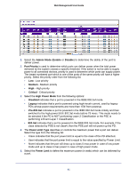
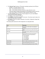
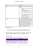
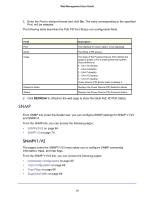
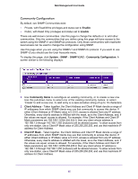
Web Management User Guide Field Units Firmware Version Power Status Total Power (Main AC) Total Power (RPS) Total Power (PD) for GSM5212P switches only Power Source Threshold Power Consumed Power Description Displays the Current PoE Unit. You can change the PoE Unit by selecting another unit ID listed here. Version of the PoE controller's FW image. Indicates the power status. Displays the total power provided by the main ac power source. Displays the total power provided by the redundant power source. Current source of system power (Main AC or RPS). System can powerup one port, if consumed power is less than this power. i.e. Consumed power can be between Nominal & Threshold Power values. The threshold power value is effected by changing System Usage Threshold. Total amount of a power which is currently being delivered to all ports. 2. To set the System Usage Threshold, enter a number from 1 to 99. This sets the threshold level at which a trap is sent if consumed power is greater than the threshold power. 3. The Power Management Mode describes or controls the power management algorithm used by the PSE to deliver power to the requesting PDs. Select Static to indicate that the power allocated for each port depends on the type of power threshold configured on the port. Select Dynamic to indicate that the power consumption on each port is measured and calculated in real-time. 4. To set the Auto Reset Mode, select Enable to reset the PSE pot without administrator intervention whenever a fault condition occurs. Select Disable to allow only the administrator to reset the PSE port whenever a fault condition is detected. 5. To set the traps, select Enable to activate the PoE traps. Select Disable to deactivate the PoE traps. The default setting is enabled. 6. Click APPLY to send the updated configuration to the switch. Configuration changes take effect immediately. PoE Port Configuration To display the Advanced PoE Port Configuration page, click System > Services > PoE > Advanced > PoE Port Configuration. A screen similar to the following displays. 60
-
 1
1 -
2
-
3
-
4
-
5
-
6
-
7
-
8
-
9
-
10
-
11
-
12
-
13
-
14
-
15
-
16
-
17
-
18
-
19
-
20
-
21
-
22
-
23
-
24
-
25
-
26
-
27
-
28
-
29
-
30
-
31
-
32
-
33
-
34
-
35
-
36
-
37
-
38
-
39
-
40
-
41
-
42
-
43
-
44
-
45
-
46
-
47
-
48
-
49
-
50
-
51
-
52
-
53
-
54
-
 55
55 -
 56
56 -
 57
57 -
 58
58 -
 59
59 -
 60
60 -
 61
61 -
 62
62 -
 63
63 -
 64
64 -
 65
65 -
66
-
67
-
68
-
69
-
70
-
71
-
72
-
73
-
74
-
75
-
76
-
77
-
78
-
79
-
80
-
81
-
82
-
83
-
84
-
85
-
86
-
87
-
88
-
89
-
90
-
91
-
92
-
93
-
94
-
95
-
96
-
97
-
98
-
99
-
100
-
101
-
102
-
103
-
104
-
105
-
106
-
107
-
108
-
109
-
110
-
111
-
112
-
113
-
114
-
115
-
116
-
117
-
118
-
119
-
120
-
121
-
122
-
123
-
124
-
125
-
126
-
127
-
128
-
129
-
130
-
131
-
132
-
133
-
134
-
135
-
136
-
137
-
138
-
139
-
140
-
141
-
142
-
143
-
144
-
145
-
146
-
147
-
148
-
149
-
150
-
151
-
152
-
153
-
154
-
155
-
156
-
157
-
158
-
159
-
160
-
161
-
162
-
163
-
164
-
165
-
166
-
167
-
168
-
169
-
170
-
171
-
172
-
173
-
174
-
175
-
176
-
177
-
178
-
179
-
180
-
181
-
182
-
183
-
184
-
185
-
186
-
187
-
188
-
189
-
190
-
191
-
192
-
193
-
194
-
195
-
196
-
197
-
198
-
199
-
200
-
201
-
202
-
203
-
204
-
205
-
206
-
207
-
208
-
209
-
210
-
211
-
212
-
213
-
214
-
215
-
216
-
217
-
218
-
219
-
220
-
221
-
222
-
223
-
224
-
225
-
226
-
227
-
228
-
229
-
230
-
231
-
232
-
233
-
234
-
235
-
236
-
237
-
238
-
239
-
240
-
241
-
242
-
243
-
244
-
245
-
246
-
247
-
248
-
249
-
250
-
251
-
252
-
253
-
254
-
255
-
256
-
257
-
258
-
259
-
260
-
261
-
262
-
263
-
264
-
265
-
266
-
267
-
268
-
269
-
270
-
271
-
272
-
273
-
274
-
275
-
276
-
277
-
278
-
279
-
280
-
281
-
282
-
283
-
284
-
285
-
286
-
287
-
288
-
289
-
290
-
291
-
292
-
293
-
294
-
295
-
296
-
297
-
298
-
299
-
300
-
301
-
302
-
303
-
304
-
305
-
306
-
307
-
308
-
309
-
310
-
311
-
312
-
313
-
314
-
315
-
316
-
317
-
318
-
319
-
320
-
321
-
322
-
323
-
324
-
325
-
326
-
327
-
328
-
329
-
330
-
331
-
332
-
333
-
334
-
335
-
336
-
337
-
338
-
339
-
340
-
341
-
342
-
343
-
344
-
345
-
346
-
347
-
348
-
349
-
350
-
351
-
352
-
353
-
354
-
355
-
356
-
357
-
358
-
359
-
360
-
361
-
362
-
363
-
364
-
365
-
366
-
367
-
368
-
369
-
370
-
371
-
372
-
373
-
374
-
375
-
376
-
377
-
378
-
379
-
380
-
381
-
382
-
383
-
384
-
385
 |
 |
