HP LaserJet M9040/M9050 Service Manual
HP LaserJet M9040/M9050 - Multifunction Printer Manual
 |
View all HP LaserJet M9040/M9050 manuals
Add to My Manuals
Save this manual to your list of manuals |
HP LaserJet M9040/M9050 manual content summary:
- HP LaserJet M9040/M9050 | Service Manual - Page 1
Service Manual - HP LaserJet M9040/M9050 | Service Manual - Page 2
- HP LaserJet M9040/M9050 | Service Manual - Page 3
HP LaserJet M9040/9050 MFP Series Service Manual - HP LaserJet M9040/M9050 | Service Manual - Page 4
to change without notice. The only warranties for HP products and services are set forth in the express warranty statements accompanying such products and services. Nothing herein should be construed as constituting an additional warranty. HP shall not be liable for technical or editorial errors - HP LaserJet M9040/M9050 | Service Manual - Page 5
-sheet stapler/stacker 8 Paper handling features 8 Stapling information 8 Multifunction finisher ...8 Paper handling features 8 Stapling information 9 Booklets ...9 Default Send to Folder Options 21 Default Print Options 22 Time/Scheduling menu ...23 Management menu ...25 Initial Setup menu - HP LaserJet M9040/M9050 | Service Manual - Page 6
server sections 67 HP Easy Printer Care ...70 Supported operating systems 70 Open the HP Easy Printer Care software 70 HP Easy Printer Care software sections 70 Use HP Web Jetadmin software ...73 HP Printer Utility for Macintosh ...74 Open the HP Printer Utility 74 Print a cleaning page ...74 - HP LaserJet M9040/M9050 | Service Manual - Page 7
...91 HP print cartridges ...91 Non-HP print cartridges ...91 Print cartridge authentication 91 HP fraud hotline ...91 Print cartridge storage ...91 Print cartridge life expectancy 92 Check the print cartridge life 92 Control panel ...92 Embedded Web server 92 HP Easy Printer Care 92 HP Web - HP LaserJet M9040/M9050 | Service Manual - Page 8
Sleep and wake ...98 5 Theory of operation Basic operation ...100 Sequence of operation ...101 Product start up sequence (turn on product 103 Timing chart ...104 Scanner subsystem ...105 Mechanical structure 105 Motors and fans 106 Basic block diagram 107 Basic system configuration 108 Scanner - HP LaserJet M9040/M9050 | Service Manual - Page 9
The image formation process 136 Print cartridge ...137 Print cartridge design 138 No-shake toner 138 operation 146 Tray 1 pickup and feed ...147 Tray 1 jam detection ...147 Tray 4 ...148 Tray 4 driver PCA ...148 Tray 4 power supply ...148 Tray 4 sequence of operation 148 Tray 4 pickup and feed - HP LaserJet M9040/M9050 | Service Manual - Page 10
ADF front cover ...161 Lower delivery roller cover 161 Reinstall the delivery roller cover 162 White board cover ...162 Copy processor/connect board 163 Reinstall the copy processor/connect board 164 Flatbed rail cover ...164 Flatbed back cover ...164 Flatbed right cover ...166 Reinstall the - HP LaserJet M9040/M9050 | Service Manual - Page 11
222 Intermediate PCA 224 Scan engine ...225 Reinstall the scan engine 229 Laser/scanner assembly 230 Delivery fan assembly ...231 Delivery motor ...233 Print engine covers ...234 Front cover ...234 Right door ...235 Right lower cover ...236 Left upper cover ...236 Reinstall the left upper cover - HP LaserJet M9040/M9050 | Service Manual - Page 12
unit (PIU) ...249 Reinstall the paper-input unit 252 Registration assembly ...252 Reinstall the registration assembly 253 Transfer-guide assembly 253 Reinstall the transfer-guide assembly 254 Left assemblies ...255 Duplexer ...255 Fuser assembly ...256 Back assemblies ...258 Formatter ...258 Low - HP LaserJet M9040/M9050 | Service Manual - Page 13
log 297 Sample event log 298 View the event log 298 Control-panel error messages ...299 User- and service-level diagnostics 322 Copy processor LEDs ...322 Troubleshooting menu ...323 Paper-path test ...324 Print a paper-path test 324 Service test ...324 Perform a service test 324 ENWW xi - HP LaserJet M9040/M9050 | Service Manual - Page 14
-level diagnostics ...326 Engine test ...326 Service menu ...326 Other diagnostics ...330 Boot-up key sequences 330 Low-level boot-up key sequence for selecting a input-tray areas 356 Clear jams from the output areas 359 Solve repeated jams ...372 Image-formation troubleshooting ...373 xii ENWW - HP LaserJet M9040/M9050 | Service Manual - Page 15
...373 Print/stop test 374 Economode ...374 Skew ...375 Copy-image defects ...375 Scanner controller PCA 377 Connector locations 379 Electrical structure 380 Wiring diagrams 381 Image-defect tables ...383 Repeating defect ruler ...391 Media troubleshooting ...392 Determine the problem source - HP LaserJet M9040/M9050 | Service Manual - Page 16
assembly ...450 Print engine internal components Services ...540 Telephone support ...540 Software utilities, drivers, and electronic information 540 HP direct ordering for accessories or supplies 540 HP service information ...540 HP service agreements 540 HP Easy Printer Care ...541 HP support - HP LaserJet M9040/M9050 | Service Manual - Page 17
FCC regulations ...548 Declaration of conformity ...549 Certificate of volatility ...550 Types of memory ...550 Volatile memory 550 Non-volatile memory 550 Hard-disk-drive memory 550 Safety statements ...551 Laser safety ...551 Canadian DOC regulations 551 VCCI statement (Japan 551 Power cord - HP LaserJet M9040/M9050 | Service Manual - Page 18
xvi ENWW - HP LaserJet M9040/M9050 | Service Manual - Page 19
1 Product basics ● Product introduction ● Product features ● Product walkaround ● Output devices ENWW 1 - HP LaserJet M9040/M9050 | Service Manual - Page 20
M9040 MFP and HP LaserJet M9050 MFP The HP LaserJet M9040 MFP and HP LaserJet M9050 MFP come standard with the following items: ● 100-sheet multipurpose input tray (Tray 1) ● Two 500-sheet input trays ● One 2,000-sheet input tray ● Automatic document feeder (ADF) ● HP Jetdirect embedded print - HP LaserJet M9040/M9050 | Service Manual - Page 21
on letter-size or International Standards Organization (ISO) A4-size paper (HP LaserJet M9050 MFP only) ● 40 ipm when scanning and printing on letter-size or ISO A4-size paper (HP LaserJet M9040 MFP only) ● 25% to 400% scalability when using the scanner glass ● 25% to 200% scalability when using - HP LaserJet M9040/M9050 | Service Manual - Page 22
User interface ● Graphical display on control panel ● Embedded Web server to gain access to support and order supplies (for network-connected products) Language and fonts ● HP Printer Command Language (PCL) 6 ● HP PCL 5e for compatibility ● Printer 17/A3 and allow printing on custom-size paper. - HP LaserJet M9040/M9050 | Service Manual - Page 23
the output device. ◦ Multifunction finisher: Provides 1,000 sheets can be assigned to individual users or workgroups for easy identification HP Jetdirect embedded print server. ● Optional analog fax card ● Optional HP Jetdirect EIO print server cards ◦ HP Jetdirect 625n gigabit Ethernet internal print - HP LaserJet M9040/M9050 | Service Manual - Page 24
, Version 1.0 HP LaserJet M9050 MFP only) ● To download the latest firmware, go to www.hp.com/go/ljm9040mfp_firmware or www.hp.com/go/ ljm9050mfp_firmware and follow the onscreen instructions. To easily send firmware updates to multiple products, use the HP Web Jetadmin software (go to www.hp.com/go - HP LaserJet M9040/M9050 | Service Manual - Page 25
display Tray 1 Right door Vertical transfer door Tray 4 Tray 3 Tray 2 Left door (behind output device) Output device Front door Duplex printing accessory (inside the product) ADF output bin Left door Printer power cable Tray 4 power cable EIO slot 1 Copy processor EIO card Product walkaround 7 - HP LaserJet M9040/M9050 | Service Manual - Page 26
available only in the print driver. See the product user guide for more information. If the stapler cannot be selected in the program or printer driver, it can be selected through the product control panel. See the product user guide for instructions. Multifunction finisher Paper handling features - HP LaserJet M9040/M9050 | Service Manual - Page 27
software programs, such as desktop publishing programs. See the user guide that came with your program for information about making booklets. If you are using a program that does not support booklet making, you can create booklets by using the HP print driver. NOTE: HP multifunction finisher staples - HP LaserJet M9040/M9050 | Service Manual - Page 28
Legal ● Ledger See the HP Multifunction Finisher User Guide at www.hp.com/support/ljm9040mfp or www.hp.com/ support/ljm9050mfp for more information about upper bin to provide 125 sheets of face-up stacking capacity ● Delivers printed jobs face down to the eight face down bins, and each bin provides - HP LaserJet M9040/M9050 | Service Manual - Page 29
2 Control panel ● Use the control panel ● Use the Administration menu ENWW 11 - HP LaserJet M9040/M9050 | Service Manual - Page 30
button. 8 Reset button Resets the job settings to factory default or user-defined default values. 9 Stop button Stops the active job. While button while the product is processing a print job, the control panel message prompts you to cancel or resume the print job). 10 Start button Begins a - HP LaserJet M9040/M9050 | Service Manual - Page 31
Home screen The home screen provides access to the product features, and it indicates the current status of the product. NOTE: Depending on how the system administrator has configured the product, the features that appear on the home screen can vary. Figure 2-2 Home screen 1 Features 2 Status line - HP LaserJet M9040/M9050 | Service Manual - Page 32
continue. Touch the Error button to see a message that describes the error. The message also has instructions for solving the problem. Warning button. The Warning button appears when the product has a problem but can continue functioning. Touch the Warning button to see a message that describes the - HP LaserJet M9040/M9050 | Service Manual - Page 33
Use the Administration menu Use the Administration menu to set up default product behavior and other global settings, such as the language and the format for date and time. NOTE: Menus can be locked by the administrator. Contact the administrator if a menu or menu item is not available. Navigate the - HP LaserJet M9040/M9050 | Service Manual - Page 34
dials that have been set up for this product Sample Pages/Fonts PCL Font List Print A list of printer control language (PCL) fonts that are currently available on the product PS Font List Print A list of postscript fonts that are currently available on the product 16 Chapter 2 Control panel - HP LaserJet M9040/M9050 | Service Manual - Page 35
default job options for each function. If the user does not specify the job options when creating Default Send To Folder Options ● Default Print Options Default Options for Originals Administration for text, pictures, or a mixture. If you select Manually Adjust, you can specify the mix of text and - HP LaserJet M9040/M9050 | Service Manual - Page 36
default output bin, if applicable, for copies. If the original document is printed close to the edges, use the Edge-To-Edge feature to avoid shadows feature with the Reduce/Enlarge feature to ensure that the entire page is printed on the copies. Select this feature to ensure that the entire image - HP LaserJet M9040/M9050 | Service Manual - Page 37
the fax header on the page. Select Prepend to print the fax header above the fax content and move the fax content down on the page. you use this menu. This is the same PIN that is used to access the Fax Printing menu. This PIN is exactly four digits. Add the date, time, senders phone number, and - HP LaserJet M9040/M9050 | Service Manual - Page 38
)" are the factory-default values. Some menu items have no default. Menu item Document File Type Output Quality Resolution Color/Black TIFF Version Values PDF (default) JPEG TIFF M-TIFF High (large file) Medium (default) Low (small file) 300 DPI 200 DPI 150 DPI (default) 75 DPI Color scan (default - HP LaserJet M9040/M9050 | Service Manual - Page 39
items have no default. Menu item Color/Black Document File Type TIFF Version Output Quality Resolution Values Color scan Black/white scan (default) PDF (default) M-TIFF TIFF JPEG TIFF 6.0 (default) TIFF (post 6.0) High (large file) Medium (default) Low (small file) 75 DPI 150 DPI (default) 200 DPI - HP LaserJet M9040/M9050 | Service Manual - Page 40
Type a value. (List of supported sizes) Millimeters Inches 1-sided (default) 2-sided Long edge Short edge Use this feature to set the default number of copies for print jobs. Choose a paper size. Configure the default paper size that is used when the user selects Custom as the paper size - HP LaserJet M9040/M9050 | Service Manual - Page 41
the week. The product exits sleep mode according to this schedule. Using a sleep schedule helps conserve energy and prepares the product for use so that users do not have to wait for it to warm up. ENWW Use the Administration menu 23 - HP LaserJet M9040/M9050 | Service Manual - Page 42
rather than having them automatically print by creating a printing schedule. For the fax printing schedule, the control panel prompts you to select days and times to print faxes. Select Change PIN to change the PIN number that users must provide to access the Fax Printing menu and the Forward Fax - HP LaserJet M9040/M9050 | Service Manual - Page 43
Management menu Administration > Management Use this menu to set up global product-management options. NOTE: Values shown with "(default)" are the factory-default values. Some menu items have no default. Table 2-8 Management menu Menu item Submenu item Values Description Network Address - HP LaserJet M9040/M9050 | Service Manual - Page 44
where xxxxxx is the last six digits of the LAN hardware (MAC) address. Specifies the method by which TCP/IPv4 parameters for the HP Jetdirect print server will be configured. Bootp: Use BootP (Bootstrap Protocol) for automatic configuration from a BootP server. DHCP (Default): Use DHCP (Dynamic Host - HP LaserJet M9040/M9050 | Service Manual - Page 45
to renew the DHCP lease. Yes: The print server renews the lease on its IP address. (Available only if Config Method is set to Manual) Configure parameters directly from the printer control panel: IP Address: The unique IP address of the printer (n.n.n.n), where n is a value from 0 to 255. Subnet - HP LaserJet M9040/M9050 | Service Manual - Page 46
can be up to 255 octets. For some networks, you may need to contact your Independent Service Provider (ISP) for the proxy server address. Type the port number used by the proxy server for client support. The port number identifies the port reserved for proxy activity on your network, and can be - HP LaserJet M9040/M9050 | Service Manual - Page 47
the DLC/LLC protocol. On (default): Enable the DLC/LLC protocol. Yes: Prints a page that contains the current security settings on the HP Jetdirect print server. No (default): A security settings page is not printed. For configuration management, specify whether the embedded Web server will accept - HP LaserJet M9040/M9050 | Service Manual - Page 48
embedded tests. Select Yes to choose all tests. Select No to select individual tests. This test helps to identify data path and corruption problems on an HP PostScript Emulation Universal Print Driver. It sends a predefined file to the product, However, the test is paperless; the file will not - HP LaserJet M9040/M9050 | Service Manual - Page 49
run continuously, select 0. If the ping test was not set for continuous operation, you can choose to print the test results. Select Yes to print results. If you select No (default), results are not printed. Specify whether to initiate the ping test. Select Yes to initiate the test, or No to not run - HP LaserJet M9040/M9050 | Service Manual - Page 50
update the data, or No to maintain the existing data. However, a refresh automatically occurs when the menu times out or you manually return to the main menu. The link speed and communication mode of the print server must match the network. The available settings depend on the product and installed - HP LaserJet M9040/M9050 | Service Manual - Page 51
Table 2-10 Jetdirect menus (continued) Menu item Submenu item Submenu item Print Protocols Values and Description 1000TX Full: 1000 Mbps, full-duplex operation Use this item to print a page that lists the configuration of the following protocols: IPX/SPX, Novell NetWare, AppleTalk, DLC/LLC. - HP LaserJet M9040/M9050 | Service Manual - Page 52
required for outgoing faxes. Phone Number Company Name Disabled Enabled (default) Use this feature to enable or disable PC Fax Send. PC Fax Send enables users to send faxes through the product from their computers if they have the Send Fax - HP LaserJet M9040/M9050 | Service Manual - Page 53
troubleshooting fax problems. Default (default) Custom This setting should be left at the default value and only changed when directed by an HP technical support directed by an HP technical support agent. Adjustment procedures associated with this setting are beyond the scope of this guide. Tone ( - HP LaserJet M9040/M9050 | Service Manual - Page 54
default) Custom When billing codes are enabled, a prompt appears that asks the user to enter the billing code for an outgoing fax. The range is between directed by an HP technical support agent. Adjustment procedures associated with this setting are beyond the scope of this guide. Off Set the - HP LaserJet M9040/M9050 | Service Manual - Page 55
> Send Setup Table 2-13 Send Setup menu Menu item Values Description Replicate MFP Enter a value (IP Address). Copy the local Send settings from one Digital Send Service Off On (default) This feature allows you to configure the product for use with an HP Digital Sending Software (DSS) - HP LaserJet M9040/M9050 | Service Manual - Page 56
Warnings Continuable Events Jam Recovery Tray Behavior Use Requested Tray Manually Feed Prompt PS Defer Media Use Another Tray Size/ Enabled (default) Disabled Use this feature to choose either the postscript or HP paper-handling model. Enabled (default) Disabled Use this feature to turn on - HP LaserJet M9040/M9050 | Service Manual - Page 57
Disabled (Default) Enabled Disabled (Default) Off (default) On Prevents print jobs from beginning to print while a walk-up user is setting up a job. Prevents non-copy print jobs from starting for a specified time after a copy job is completely printed. Use this feature to turn on no-wait scanning - HP LaserJet M9040/M9050 | Service Manual - Page 58
is printed when the product encounters a PDF error. Select the printer language that the product should use. Normally you should not change the language. If you change the setting to a specific language, the product does not automatically switch from one language to another unless specific software - HP LaserJet M9040/M9050 | Service Manual - Page 59
that would cause blank pages to be printed. When Yes is selected, form feeds are ignored if the page is blank. Standard (default) Classic Use this feature to select and maintain input trays by number when you are not using the product driver or when the software program has no option for tray - HP LaserJet M9040/M9050 | Service Manual - Page 60
Modes Resolution Test Page Source Adjust Tray Standby Fuser Mode Restore Modes Print (button) Print a test page for setting the registration. Follow the instructions that are printed on the page to adjust each tray. All trays Tray : Tray : (choose - HP LaserJet M9040/M9050 | Service Manual - Page 61
15 Print Quality menu (continued) Menu item Submenu item Calibration/Cleaning Create Cleaning Page Values Create (button) Process Cleaning Page Process (button) Description Generate a page for cleaning excess toner off the pressure roller in the fuser. The page has instructions that guide you - HP LaserJet M9040/M9050 | Service Manual - Page 62
only Print after receive errors only Fax Transmit Signal Loss (available if the fax accessory is installed) A value between 0 and 30. The default is 0. Set loss levels to compensate for phone-line signal loss. Do not modify this setting unless requested to do so by an HP service representative - HP LaserJet M9040/M9050 | Service Manual - Page 63
how many pages should be sent from the specified source as part of the test. Follow the on-screen instructions. Provides a series of prompts that the user can follow to discover if the printer is functioning properly. It also makes sure that paper is not in the paper path. Continuous value from - HP LaserJet M9040/M9050 | Service Manual - Page 64
has been installed. Lock Carriage Lock (button) Use the feature to lock the carriage. To unlock the carriage, turn the product off and then on. Service menu Administration > Service The Service menu is locked and requires a PIN for access. This menu is intended for use by authorized - HP LaserJet M9040/M9050 | Service Manual - Page 65
3 Paper and print media ● Understand paper and print media use ● Supported paper and print media sizes ● Custom paper sizes ● Special paper or print media guidelines ● Load paper and print media ● Configure trays ● Select the output bin ENWW 47 - HP LaserJet M9040/M9050 | Service Manual - Page 66
in this user guide. Paper or print media that does not meet these guidelines might cause the following problems: ● Poor print quality ● Increased jams ● Premature wear on the product, requiring repair For best results, use only HP-brand paper and print media designed for laserjets or multiuse - HP LaserJet M9040/M9050 | Service Manual - Page 67
of paper sizes, and it adapts to various media. NOTE: To obtain best print results, select the appropriate paper size and type in your print driver before printing. Table 3-1 Supported paper and print media sizes Size Dimensions Tray 1, Letter R, A4 Trays 2 and 3, Tray 4, Letter Letter R, A4 - HP LaserJet M9040/M9050 | Service Manual - Page 68
are sizes that are within the minimum- and maximum-size guidelines for the product but are not listed in the supported paper sizes table. When using a supported custom size, specify the custom size in the print driver, and load the paper in a tray that supports custom sizes. 50 Chapter 3 Paper and - HP LaserJet M9040/M9050 | Service Manual - Page 69
or print media guidelines This product supports printing on special media. Use the following guidelines to obtain satisfactory results. When using special paper or print media, be sure to set the type and size in your print driver to obtain the best print results. CAUTION: HP LaserJet printers use - HP LaserJet M9040/M9050 | Service Manual - Page 70
media, see Supported paper and print media sizes on page 49. 1. Open Tray 1. Figure 3-1 Load Tray 1 (1 of 3) 2. Load paper according to size and finishing options. Figure 3-2 Load Tray 1 (2 of 3) CAUTION: To avoid jams, print sheets of labels one sheet at a time. 3. Adjust the paper guides so they - HP LaserJet M9040/M9050 | Service Manual - Page 71
up to 500 sheets of standard media. Tray 4 holds up to 2,000 sheets of standard media. For information about paper specifications, see Supported paper and print media sizes on page 49. Load detectable standard-size paper in Trays 2, 3, and 4 Follow this procedure to load detectable standard-size - HP LaserJet M9040/M9050 | Service Manual - Page 72
set the guide to the correct paper size. Figure 3-6 Load Trays 2, 3, and 4 (3 of 6) 4. Load (orient) the paper according to size. Figure 3-7 Load Trays 2, 3, and 4 (4 of 6) 5. Set the Custom/Standard switch to Standard. Figure 3-8 Load Trays 2, 3, and 4 (5 of 6) 54 Chapter 3 Paper and print media - HP LaserJet M9040/M9050 | Service Manual - Page 73
mm) CAUTION: To avoid a jam, never add or remove paper from a tray while printing from that tray. 1. Open the tray until it stops. Figure 3-10 Load undetectable standard front paper guide, and slide the guide all the way out. 3. Press the tab on the left paper guide, and slide the guide all the way - HP LaserJet M9040/M9050 | Service Manual - Page 74
paper in Trays 2, 3, and 4 (4 of 6) NOTE: When loading Tray 4, make sure that the paper guide lock is in the up position. 7. Set the Custom/Standard switch to Custom. Figure 3-14 Load undetectable standard 4 (6 of 6) Load custom media in Trays 2, 3, and 4 56 Chapter 3 Paper and print media ENWW - HP LaserJet M9040/M9050 | Service Manual - Page 75
To avoid a jam, never add or remove paper from a tray while printing from that tray. 1. Open the tray until it stops. Figure 3-16 Load custom media in Trays 2, 3, and 4 (1 of 6) 2. Press the tab on the front (X) paper guide and slide the guide all the way out. 3. Press the tab on the left (Y) paper - HP LaserJet M9040/M9050 | Service Manual - Page 76
. You will need this information for a later step. NOTE: When loading Tray 4, make sure that the paper guide lock is in the up position. 9. Close the tray. The product control panel might show the tray media type custom media in Trays 2, 3, and 4 (6 of 6) 58 Chapter 3 Paper and print media ENWW - HP LaserJet M9040/M9050 | Service Manual - Page 77
does not appear if you are printing from Tray 1 and Tray 1 is configured for Any Size and Any Type. NOTE: If you have used other HP LaserJet printer models, you might be accustomed to configuring Tray 1 to First mode or Cassette mode. On the HP LaserJet M9040/M9050 MFP, setting Tray 1 size and type - HP LaserJet M9040/M9050 | Service Manual - Page 78
by Type or Size, select Type or Size from the Page Setup dialog box, the Print dialog box, or the Print Properties dialog box depending on the software program. TIP: If you print on a certain type or size of media often, configure a tray for that type or size. Then, whenever you select that type - HP LaserJet M9040/M9050 | Service Manual - Page 79
bins For best results, select an output location using the software program or print driver. Stacker or stapler/stacker output bins The 3,000-sheet stacker eight face down bins to individual users or workgroups. Multifunction finisher output bins The multifunction finisher includes an upper bin ( - HP LaserJet M9040/M9050 | Service Manual - Page 80
Where and how you make selections depends on your program or driver. Set the default output location from the product control panel. 1. Scroll to and touch Administration. 2. Touch Default Job Options. 3. Touch Default Print Options. 4. Touch Output Bin. 5. Touch the desired output bin. Copying You - HP LaserJet M9040/M9050 | Service Manual - Page 81
● Information pages ● Embedded Web server ● HP Easy Printer Care ● Use HP Web Jetadmin software ● HP Printer Utility for Macintosh ● Security features ● Set the real-time clock ● Clean the product ● Configure alerts ● Manage supplies ● Printer maintenance kit ● Manage memory ● Economy settings - HP LaserJet M9040/M9050 | Service Manual - Page 82
The following table provides the instructions for printing the information pages. Page description How to print the page from the product Status Pages. 4. Touch Supplies Status Page. 5. Touch Print. Usage page NOTE: If you are using non-HP supplies, the supplies status page might not show the - HP LaserJet M9040/M9050 | Service Manual - Page 83
corresponding report: ◦ Fax Activity Log ◦ Fax Call Report ◦ Billing Codes Report ◦ Blocked Fax List ◦ Speed Dial List 5. Touch Print. For more information, see the fax guide that came with the product. Font lists 1. From the Home screen, touch Administration. Shows which fonts are currently - HP LaserJet M9040/M9050 | Service Manual - Page 84
Guide, which is on the HP LaserJet M9040 MFP and HP LaserJet M9050 MFP software CD. Open the embedded Web server by using a network connection 1. In a supported Web browser on your computer, type the device IP address or host name in the address/URL field. To find the IP address or host name, print - HP LaserJet M9040/M9050 | Service Manual - Page 85
shows the life remaining of HP supplies with 0% indicating that a supply is empty. The page also shows the type and size of print paper set for each tray Manager: Allows you to determine which product functions will require a user to provide log-in information in order to use those functions. - HP LaserJet M9040/M9050 | Service Manual - Page 86
and export address book and user information to and from the HP Jetdirect print server. NOTE: The Networking tab can be password-protected. Other links ● Contains links that connect you to the Internet ● HP Instant Support™: Connects you to the HP Web site to help you find solutions. This service - HP LaserJet M9040/M9050 | Service Manual - Page 87
Tab or section Options NOTE: You must have Internet access in order to use any of these links. If you use a dial-up connection and did not connect when you first opened the embedded Web server, you must connect before you can visit these Web sites. Connecting might require that you close the - HP LaserJet M9040/M9050 | Service Manual - Page 88
status ● Setting up alerts ● Viewing product documentation ● Gaining access to troubleshooting and maintenance tools ● Printing usage reports ● Fixing problems with HP drivers, software, and product firmware You can use HP Easy Printer Care when the product is directly connected to your computer or - HP LaserJet M9040/M9050 | Service Manual - Page 89
: Provides links to information about HP Easy Printer Care, to advanced product settings, and to product usage reports. ● Troubleshooting and Help: Provides links to tools that you can use to resolve problems, to online product support information, and to online HP experts. ● About: Provides general - HP LaserJet M9040/M9050 | Service Manual - Page 90
is available from the software, firmware, and HP printer drivers. You can accept or decline each Overview and Support tabs. recommended update information on options for purchasing your selected supplies. ● Print Shopping List button: Prints the information for the supplies that have the Order - HP LaserJet M9040/M9050 | Service Manual - Page 91
Use HP Web Jetadmin software HP Web Jetadmin is a Web-based software solution for remotely installing, monitoring, and troubleshooting network-connected peripherals. The intuitive browser interface simplifies cross-platform management of a wide range of devices, including HP and non-HP devices. - HP LaserJet M9040/M9050 | Service Manual - Page 92
cleaning page if the product is not printing jobs at the expected quality level. 1. Open the HP Printer Utility. 2. In the Configuration Settings list, select Cleaning. 3. Click Print Cleaning Page to print the cleaning page. Print a configuration page Print a configuration page to view the product - HP LaserJet M9040/M9050 | Service Manual - Page 93
support Web pages. 1. Open the HP Printer Utility. 2. In the Configuration Settings list, select HP Support. 3. Click one of the following buttons: ● Instant Support example, when a print-ready file (such as a .PS or .PCL file) is sent, the product prints the file. 1. Open the HP Printer Utility. 2. - HP LaserJet M9040/M9050 | Service Manual - Page 94
OK. 4. Click Upload to load the firmware file. Activate the two-sided printing (duplexing) mode Turn on the two-sided printing feature on products equipped with automatic duplexers. 1. Open the HP Printer Utility. 2. In the Configuration Settings list, select Duplex mode. 3. Select Enable Duplex - HP LaserJet M9040/M9050 | Service Manual - Page 95
tray settings from the computer. 1. Open the HP Printer Utility. 2. In the Configuration Settings list, select Tray Configuration. 3. In the Trays list, select the tray to be configured. NOTE: To make the selected tray the default tray for printing, click Make Default. 4. In the Default Media - HP LaserJet M9040/M9050 | Service Manual - Page 96
with the product, such as a low toner level in a print cartridge. 1. Open the HP Printer Utility. 2. In the Configuration Settings list, select E-mail to which you want the e-mail alerts sent. NOTE: If your product supports e-mail lists, you can make alerts lists for specific events the same way - HP LaserJet M9040/M9050 | Service Manual - Page 97
the embedded Web server to prevent unauthorized users from changing the product settings. 1. Open data from unauthorized access. This feature can securely erase print and copy jobs from the hard drive. Secure ), stored fax files, address books, and HP and third-party applications. NOTE: Stored jobs - HP LaserJet M9040/M9050 | Service Manual - Page 98
and PIN. Optional HP Digital Send Software supports Windows SPNEGO, LDAP users from changing the configuration settings such as the SMTP server. The following procedure describes how to restrict access to the control-panel menus by using the HP Web Jetadmin software. (See Use HP Web Jetadmin software - HP LaserJet M9040/M9050 | Service Manual - Page 99
list, select Configure. 5. Select Security from the Configuration Categories list. 6. Type a Device Password. 7. In the Control Panel Access section, select Maximum Lock. This prevents unauthorized users from gaining access to configuration settings. ENWW Security features 81 - HP LaserJet M9040/M9050 | Service Manual - Page 100
to set the date and time settings. The date and time information is attached to stored print, fax, and digital-send jobs, so you can identify the most recent versions of stored print jobs. 1. On the control panel, scroll to and touch Administration. 2. Touch Time/Scheduling. 3. Touch Date/Time - HP LaserJet M9040/M9050 | Service Manual - Page 101
Cleaning Page. The product prints a cleaning page. 5. Follow the instructions printed on the cleaning page. Clean the product hardware To maintain print quality, clean the product thoroughly: ● every time you change the print cartridge ● whenever print-quality problems occur Clean the outside of - HP LaserJet M9040/M9050 | Service Manual - Page 102
a dry, lint-free cloth, wipe any residue from the paper path area, the registration roller, and the print cartridge cavity. Figure 4-4 Clean the paper path (3 of 6) 4. Replace the print cartridge. Figure 4-5 Clean the paper path (4 of 6) 5. Rotate the green handle into the locked position. Figure - HP LaserJet M9040/M9050 | Service Manual - Page 103
6. Close the front cover, reconnect all cables, and turn the product on (button in). Figure 4-7 Clean the paper path (6 of 6) Clean the outside of the product ● Clean the outside of the product if it is visibly marked. ● Use a soft, lint-free cloth dampened with water. Clean the touchscreen ● Clean - HP LaserJet M9040/M9050 | Service Manual - Page 104
2. Locate the top and bottom ADF glass strips. Figure 4-9 Clean the ADF delivery system (2 of 5) 3. Clean the glass strips by wiping them gently with a clean, damp, lint-free cloth. 4. Locate the white, vinyl backing. Figure 4-10 Clean the ADF delivery system (3 of 5) 5. Locate the white, vinyl - HP LaserJet M9040/M9050 | Service Manual - Page 105
CAUTION: Clean this area only if you see copy defects such as streaks, and you notice dust inside the glass strip. Cleaning this area frequently could introduce dust into the product. 1. Open the ADF cover. Figure 4-13 Clean the top ADF glass strip (1 of 4) 2. Locate the latch that releases the top - HP LaserJet M9040/M9050 | Service Manual - Page 106
5. Close the ADF cover. Figure 4-16 Clean the top ADF glass strip (4 of 4) Clean the ADF rollers You should clean the rollers in the ADF if you are experiencing misfeeds or if your originals show marks as they exit the ADF. 1. Open the top cover. CAUTION: Clean the rollers only if you experience - HP LaserJet M9040/M9050 | Service Manual - Page 107
water directly onto the rollers. Doing so might damage the product. 8. Close the ADF cover. Figure 4-22 Clean the ADF rollers (6 of 6) 9. Close the delivery guide and wipe its outside surface with the cloth. ENWW Clean the product 89 - HP LaserJet M9040/M9050 | Service Manual - Page 108
You can use HP Web Jetadmin or the embedded Web server to configure the system to alert you of problems with the product. account to which the alerts should be forwarded Software HP Web Jetadmin Embedded Web server Information location See the HP Web Jetadmin Help system for details on alerts - HP LaserJet M9040/M9050 | Service Manual - Page 109
under the product warranty. If the non-HP print cartridge was sold to you as a genuine HP product, see HP fraud hotline on page 91. Print cartridge authentication The HP LaserJet M9040 MFP and HP LaserJet M9050 MFP automatically authenticate the print cartridges when the cartridges are inserted into - HP LaserJet M9040/M9050 | Service Manual - Page 110
ISO/IEC 19752. Actual yield depends on specific use. Check the print cartridge life You can check the print cartridge life using the control panel, the embedded Web server, the product software, HP Easy Printer Care, or HP Web Jetadmin. Control panel 1. From the Home screen, touch Administration - HP LaserJet M9040/M9050 | Service Manual - Page 111
not covered under warranty. To ensure optimum print quality, HP recommends that a new printer maintenance kit be installed approximately every 350, you should replace the printer maintenance kit, contact the support center at www.hp.com/support/ljm9040mfp or www.hp.com/ support/ljm9050mfp. When the - HP LaserJet M9040/M9050 | Service Manual - Page 112
(SIMMs) used on other HP LaserJet products are not compatible with this product. For ordering information, go to www.hp.com/support/ljm9040mfp or www.hp.com/support/ljm9050mfp. Determine memory requirements The amount of memory required depends on the types of documents you print. The product can - HP LaserJet M9040/M9050 | Service Manual - Page 113
3. Turn the product off, and then disconnect the power cord and all cables. Figure 4-24 Install DDR memory DIMMs (2 of 8) 4. Loosen the two captive thumb screws on the back of the product. Figure 4-25 Install DDR memory DIMMs (3 of 8) 5. Grasp the screws and pull the formatter board out of the - HP LaserJet M9040/M9050 | Service Manual - Page 114
7. Press the DIMM straight into the slot (press firmly). Make sure the locks on each side of the DIMM snap inward into place. (To remove a DIMM, the locks must be released.) Figure 4-28 Install DDR memory DIMMs (6 of 8) 8. Slide the formatter board back into the product and tighten the two screws. - HP LaserJet M9040/M9050 | Service Manual - Page 115
an error message appears, a DIMM might be installed incorrectly. 2. Print the configuration page. 3. Check the memory section on the configuration page the DIMM in a different slot. NOTE: If you installed a printer language (personality), check the Installed Personalities and Options section on the - HP LaserJet M9040/M9050 | Service Manual - Page 116
Economy settings Sleep and wake Set the sleep delay Use the sleep-delay feature to choose the period of time to allow the product to be idle before it enters sleep mode. The default setting is 45 minutes. 1. Scroll to and touch Administration. 2. Touch Time/Scheduling. 3. Touch Sleep Delay. 4. Touch - HP LaserJet M9040/M9050 | Service Manual - Page 117
5 Theory of operation ● Basic operation ● Engine control system ● Formatter system ● Laser/scanner system ● Image formation system ● Pickup and feed system ● Tray 1 ● Tray 4 ENWW 99 - HP LaserJet M9040/M9050 | Service Manual - Page 118
Basic operation Product operation is composed of the following systems: ● Engine control ● Formatter ● Laser/scanner ● Image formation ● Pickup and feed Figure 5-1 Product operation systems 100 Chapter 5 Theory of operation ENWW - HP LaserJet M9040/M9050 | Service Manual - Page 119
Check for fuser wrapping jam ● Check door open/sleep Standby (STBY) ● After the WAIT state or after the Last Rotation ● state until a print reservation command comes from the formatter ● Start fuser-roller temperature control and delivery motor. Run fuser control (fuser roller temperature at 180 - HP LaserJet M9040/M9050 | Service Manual - Page 120
command until the ● Run fuser/delivery, drum, scanner, and fan motors. primary DC bias is turned off ● Set fuser control to print temperature: fuser 190°C (374°F). ● Send engine-to-formatter output signal. ● Send formatter-to-engine input signal. ● Run paper-feed control. ● Run image control - HP LaserJet M9040/M9050 | Service Manual - Page 121
Table 5-2 Failure sequence State Period Operation JAM After product is turned on until the end of the ● LSTR state ● Check sensors. Stop drives. ● Set status. DOOR OPEN ● After product is turned on until the end of the ● LSTR period ● Check door open. Stop drives. Set status. ● Await door - HP LaserJet M9040/M9050 | Service Manual - Page 122
15. Turn off fuser motor, drum motor, transfer negative bias, pressure bias, and SL501 once the fuser reaches target temperature. 16. Initialize standby mode. Timing chart Figure 5-3 Operational timing chart 104 Chapter 5 Theory of operation ENWW - HP LaserJet M9040/M9050 | Service Manual - Page 123
Scanner subsystem Mechanical structure The ADF optical assembly and the flatbed optical assembly each has a complete scanning system. This enables single-pass duplex scanning. NOTE: The lamps (callout 1) cannot be replaced separately. You must replace the entire optical assembly. Figure 5-4 Scanning - HP LaserJet M9040/M9050 | Service Manual - Page 124
Figure 5-5 Scanner system mechanical structure 4 6 7 2 1 53 Table 5-4 Scanner system mechanical structure Number Part 1 Pickup roller 2 Separation belt assembly (belt, timing) 3 Feed roller assembly 4 Upper registration roller assembly 5 Lower registration roller assembly 6 Upper - HP LaserJet M9040/M9050 | Service Manual - Page 125
The three fans are for the ADF, the flatbed, and the power supply: ● The ADF fan assembly includes a fan housing. The ADF fan is an intake fan. NOTE: The ADF fan can be ordered separately or with its plastic housing. ● The flatbed fan assembly includes a filter. The flatbed fan is an intake fan. - HP LaserJet M9040/M9050 | Service Manual - Page 126
formatter completes the processing. The data is then passed to the DC controller for printing, or is passed to a computer for digital sending. Figure 5-7 Scanner system ● Image processing system ◦ ADF analog processor ◦ ADF CCD (charge coupled device) driver 108 Chapter 5 Theory of operation ENWW - HP LaserJet M9040/M9050 | Service Manual - Page 127
processor ◦ Flatbed CCD driver ● Scanner control system print engine power supply. Make sure you unplug the product before beginning any service. Table 5-6 Power supply assembly ratings Product Volts Frequency Amps Watts (typical) Typical Electricity Consumption (TEC) HP LaserJet M9050 MFP - HP LaserJet M9040/M9050 | Service Manual - Page 128
Vac: minimum recommended current capacity = 6.5-amp dedicated circuit HP LaserJet M9040 MFP 100-127 Vac ± 10 50/60 Hz ± 2 Hz percent 220-240 Vac ± 10 percent 100-127 Vac: minimum recommended current capacity = 15-amp dedicated circuit Print: 1,022; Copy: 1,030; Ready: 331; Sleep 1: 244; Sleep - HP LaserJet M9040/M9050 | Service Manual - Page 129
Pushing the Sleep button while the product is in the Ready (waiting for a print job) state begins the sleep mode (sleep mode 2). Pushing the Sleep button of less than that used when the product is in the Ready (waiting for a print job) state, and more than that used when in sleep mode 2. Sleep mode - HP LaserJet M9040/M9050 | Service Manual - Page 130
power supply. The remote switch is employed as a power switch of the scan engine. Of the voltages supplied from the print engine dc controller to the power supply of the scan engine, 3.3 vdc are used as a remote signal. The signal is supplied to the power supply - HP LaserJet M9040/M9050 | Service Manual - Page 131
the problem in the failure loads, wait about two minutes, and then turn on the based on a scan command from the CP. ● CPU (IC7): According to the control programs stored in the ROM (IC5), the CPU performs: ◦ image scanner sequence control ◦ communication with the copy processor control ◦ pickup - HP LaserJet M9040/M9050 | Service Manual - Page 132
backup adjustment data of the scanner, such as the leading-edge registration adjustment values and horizontal registration adjustment values. ● ROM (IC5): Stores the scanner control programs. ● Pickup motor driver IC (IC3): Drives the pickup motor based on commands from the CPU. ● Delivery motor - HP LaserJet M9040/M9050 | Service Manual - Page 133
(CRMOT) to the flatbed motor to drive the flatbed optical unit forward to scan from the glass, or backward when scanning from the ADF frontside. HP-S is the flatbed home position detection sensor. When the flatbed optical unit is in the home position, a signal - HP LaserJet M9040/M9050 | Service Manual - Page 134
Flatbed optical unit operation The ADF optical unit is located 26.5 mm (1 in) from the flatbed optical unit when the flatbed optical unit is in the ADF scanning position. When a two-sided original document is copied from the ADF, the first side begins copying before the second side of the two-sided - HP LaserJet M9040/M9050 | Service Manual - Page 135
Flatbed document size detection Figure 5-16 Flatbed document size detection Sensor names ● Flatbed document detection sensor: SCNSIZE1S (only detects the document on the glass) ● Flatbed document size detection sensor (1): SCNSIZE2S size sensor ● Flatbed document size detection sensor (2): - HP LaserJet M9040/M9050 | Service Manual - Page 136
light. When there is not a document on the glass, the emitted light passes through the glass and the photoreceptor cannot receive the emitted light. Figure 5-17 Functions operation 118 Chapter 5 Theory of operation ENWW - HP LaserJet M9040/M9050 | Service Manual - Page 137
ADF angle detection The SCB performs the detection by monitoring an output of the ADF angle detection sensor (PI-1). The output of the PI-1 is "H" when the ADF unit is opened. When the angle between the glass and the ADF is less than 30 degrees, the sensor lever interrupts the PI-1 and the output of - HP LaserJet M9040/M9050 | Service Manual - Page 138
Figure 5-19 ADF document exposure control ADF document feed control ADF document feed control is performed to pass paper over the optical units for exposure. The ADF document feed control process begins when the SCB sends signals. The shutter solenoid helps to align the paper, and the weight plate " - HP LaserJet M9040/M9050 | Service Manual - Page 139
● WTSOL: weight solenoid ● DMOT: delivery motor Figure 5-20 ADF document feed control Pickup and feed operation 1. The shutter solenoid is turned on when the SCB receives a scan command, and the document shutters drop. 2. About 200 milliseconds after the shutter solenoid is turned on, the pickup - HP LaserJet M9040/M9050 | Service Manual - Page 140
transferred through the intermediate PCA to the CP. The CP calculates the size of the document based on the signals in the service menu. ADF document size detection terminology ● TRS-S: ADF document length detection (short) ● TRL-S: ADF document length detection (long) ● TRVR: ADF width detection - HP LaserJet M9040/M9050 | Service Manual - Page 141
ADF feeder sensors ● REG-S (registration sensor): detects when paper is approaching the registration rollers. ● TMG-S (timing sensor): verifies that paper is moving through the paper path. ● SKR-S (back skew sensor) ● SKF-S (front skew sensor) NOTE: The ADF has a document detection sensor that - HP LaserJet M9040/M9050 | Service Manual - Page 142
Figure 5-23 Document skew jam Scanned data flow The product has a scan engine with 600 by 600 ppi (pixels per inch) resolution. It has three channels (red, blue, and green) with 10 bits per channel, resulting in the equivalent of a 30-bit scan engine. 124 Chapter 5 Theory of operation ENWW - HP LaserJet M9040/M9050 | Service Manual - Page 143
Analog data is captured by the CCD driver circuit and converted to digital data on the analog desired file type (TIFF, MTIFF, JPEG, or PDF). Figure 5-24 Scanned data flow Copy processor The copy processor (CP) is the link between the formatter in the print engine and the SCB in the scan engine. - HP LaserJet M9040/M9050 | Service Manual - Page 144
SCB. After the scanning process is completed by the SCB, the scanned data is sent to the CP. The CP processes the image and sends the image data to the formatter. Figure 5-25 Copy processor Scanning process control signals The CP controls the following scanning process control signals: ● ADF unit - HP LaserJet M9040/M9050 | Service Manual - Page 145
image. 7. The CP sends the image data to the formatter. 8. The formatter further processes the image data (if required). 9. The image data is then either printed or digitally sent depending on what the user specified at the beginning of the process. ENWW Basic operation 127 - HP LaserJet M9040/M9050 | Service Manual - Page 146
control system The engine control system coordinates the laser/scanner system, the image formation system, and the pickup and feed system according to instructions from the formatter. It consists of the DC controller PCA, the high-voltage power supply circuit, and the low-voltage power supply unit - HP LaserJet M9040/M9050 | Service Manual - Page 147
DC controller PCA Figure 5-27 DC controller PCA The DC controller PCA manages the operational sequences of the product. The following table lists the DC controller components and their functions. Table 5-8 DC controller operations Component Function CPU (IC201) ● Controls sequences of the - HP LaserJet M9040/M9050 | Service Manual - Page 148
ASIC (IC202) ● Receives instructions from the CPU ● Controls and ASIC when the product is turned on EEPROM (IC204) Pickup motor driver IC (IC205) Pickup roller up-and-down motor IC (IC206) ● circuit The high-voltage power supply receives instructions from the DC controller to apply high- - HP LaserJet M9040/M9050 | Service Manual - Page 149
It also detects the toner level. Figure 5-28 High-voltage power supply Each circuit serves a specific purpose: Table 5-9 High-voltage power supply circuits Bias generation circuit Purpose Primary charging bias The circuit applies bias to the primary charging roller to spread a uniform negative - HP LaserJet M9040/M9050 | Service Manual - Page 150
drum. Pre-transfer upper guide bias The circuit prevents toner from adhering to the pre-transfer upper guide. Transfer bias The circuit detection The circuit monitors toner level via two antennae inside the print cartridge. Low-voltage power supply The low-voltage power supply consists - HP LaserJet M9040/M9050 | Service Manual - Page 151
Table 5-10 Fuser control circuit components Component Purpose Main heater (H1) Heats the center of the fuser roller Sub-heater (H2) Heats both ends of the fuser roller Lower heater (H3) Heats the pressure roller Upper thermistor (TH1) Monitors the surface temperature of the fuser roller - HP LaserJet M9040/M9050 | Service Manual - Page 152
ROM Stores fonts and microprocessor control programs RAM Stores printing and font information and temporarily stores print-image data before it sent to the print to supply power when the product is turned off. HP Jetdirect Inside (JDI) JDI is an Ethernet interface that is part of the - HP LaserJet M9040/M9050 | Service Manual - Page 153
Laser/scanner system The laser unit of the laser/scanner system includes two laser diodes which enable scanning two lines simultaneously. The laser/scanner PCA turns on the laser diodes based on signals from the DC controller and the formatter systems. The laser beams strike a six-sided mirror that - HP LaserJet M9040/M9050 | Service Manual - Page 154
, it reflects the beams through a set of focusing lenses and onto another mirror, which reflects the beams through a slot in the top of the print cartridge and onto the photosensitive drum. The beams sweep from left to right on the drum discharging the negative potential wherever they strike the - HP LaserJet M9040/M9050 | Service Manual - Page 155
negatively charged (unexposed) areas. Pre-transfer The pre-transfer upper guide receives bias to prevent toner from adhering to it from the toner receptacle. Print cartridge Figure 5-32 Layout of the print cartridge 5 12 4 3 13 12 8 11 10 9 6 7 Table 5-13 Print cartridge components - HP LaserJet M9040/M9050 | Service Manual - Page 156
of toner at the point when print fading occurs. Cartridge memory The print cartridge includes RAM (callout 6) to record its condition and to provide information to the product. The memory controller reads and writes to the memory after receiving instructions from the DC controller, which monitors - HP LaserJet M9040/M9050 | Service Manual - Page 157
antenna and a flat antenna to enable the DC controller to detect toner-level. Whenever the power is turned on, a door cover is closed, or a print operation is performed, the DC controller sets the developing bias signal, and the developing AC bias circuit sends a signal to the toner level circuit - HP LaserJet M9040/M9050 | Service Manual - Page 158
face-down bin. When the product is turned on, the lifter lifts the stack of media to the pickup area in preparation for printing. When the DC controller receives a print command, the pickup roller starts rotating and lowers to the paper surface. This feeds a sheet of paper to the feed rollers and - HP LaserJet M9040/M9050 | Service Manual - Page 159
Jam detection The product can detect the following jams: Table 5-14 Jam detection Jam Causes and conditions Pickup 1 delay jam Pickup 2 delay jam Media fails to reach Tray 2 feed sensor A (PS1402) or Tray 3 feed sensor A (PS1404) within 3.2 seconds after pickup begins. ● Media fails to reach - HP LaserJet M9040/M9050 | Service Manual - Page 160
Table 5-14 Jam detection (continued) Jam Causes and conditions ◦ Tray 2 feed sensor B (PS1401) ◦ Tray 3 feed sensor B (PS1403) ◦ Face-down bin delivery sensor (PS1451) Figure 5-33 Pickup and feed system sensors and switches Table 5-15 Pickup and feed system sensors and switches Sensor or - HP LaserJet M9040/M9050 | Service Manual - Page 161
Table 5-15 Pickup and feed system sensors and switches (continued) Sensor or switch Description PS2 Registration paper sensor PS501 Fuser delivery sensor PS502 Fuser jam sensor PS1401 Tray 2 feed sensor B PS1402 Tray 2 feed sensor A PS1403 Tray 3 feed sensor B PS1404 Tray 3 feed - HP LaserJet M9040/M9050 | Service Manual - Page 162
Figure 5-34 Pickup and feed system motors and solenoids Table 5-16 Pickup and feed system motors and solenoids Motor or solenoid Description DCM1 Fuser/delivery motor DCM2 Main/drum motor SMT1 Pickup roller up and down motor SMT2 Lifter motor SMT3 Pickup motor 144 Chapter 5 Theory of - HP LaserJet M9040/M9050 | Service Manual - Page 163
Table 5-16 Pickup and feed system motors and solenoids (continued) Motor or solenoid Description SL1 Face-up solenoid SL501 Jam detection lever drive solenoid CL1 Registration roller drive clutch CL2 Pre-registration roller drive clutch ENWW Pickup and feed system 145 - HP LaserJet M9040/M9050 | Service Manual - Page 164
Tray 1 Tray 1 accommodates a wide variety of media. It picks up and feeds media directly into the paper path. Tray 1 driver PCA Tray 1 includes a driver PCA with a four-bit microcomputer (CPU-IC2501) that controls the operational sequence and the serial communications with the DC controller. The CPU - HP LaserJet M9040/M9050 | Service Manual - Page 165
4. Feeds the media to the between-page adjustment position, turns off CL2501, and feeds media into the paper path. 5. Receives a feed-stop command, stops the motor, and returns to a standby state Tray 1 pickup and feed The pickup roller moves up and down to feed media into the paper path. This - HP LaserJet M9040/M9050 | Service Manual - Page 166
The +5 V is supplied to the sensors and also to the ICs on the driver PCA. The power unit utilizes a standalone switch so that Tray 4 can be powered paper deck starts lifting the stack to the pickup position. When the formatter instructs Tray 4 to deliver media, the drive rollers pick up a sheet and - HP LaserJet M9040/M9050 | Service Manual - Page 167
product. When the media reaches the merge-point in the product, the driver PCA checks for a merge-point permission command sent from the formatter. If level sensor PCA. The combination of these sensors determines the level of the print media loaded in Tray 4. The paper size is detected by the paper - HP LaserJet M9040/M9050 | Service Manual - Page 168
150 Chapter 5 Theory of operation ENWW - HP LaserJet M9040/M9050 | Service Manual - Page 169
● Removal and replacement strategy ● Repair notices ● Electrostatic discharge ● Required tools ● Product orientation ● Scanner assembly covers ● Scan engine internal assemblies ● Print engine covers ● Front assemblies ● Right assemblies ● Left assemblies ● Back assemblies ● Tray 4 ENWW 151 - HP LaserJet M9040/M9050 | Service Manual - Page 170
CAUTION: Always remove the print cartridge before removing or replacing assemblies and parts (see Print cartridge on page 242). IMPORTANT: Put the print cartridge in its original print-cartridge bag, or, wire loops, lance points, or wire-harness guides. 152 Chapter 6 Removal and replacement ENWW - HP LaserJet M9040/M9050 | Service Manual - Page 171
Electrostatic discharge CAUTION: Some parts are sensitive to electrostatic discharge (ESD). Look for the ESD reminder when removing product parts. Always perform service work at an ESD-protected workstation or mat. If an ESD workstation or mat is not available, ground yourself by touching the - HP LaserJet M9040/M9050 | Service Manual - Page 172
Product orientation Front and right side orientation Figure 6-1 View of the front and right sides 1 2 Table 6-1 Product front and right sides 1 Front side 2 Right side 154 Chapter 6 Removal and replacement ENWW - HP LaserJet M9040/M9050 | Service Manual - Page 173
Back and left side orientation Figure 6-2 View of the back and left sides 1 2 Table 6-2 Product back and left sides 1 Back side 2 Left side ENWW Product orientation 155 - HP LaserJet M9040/M9050 | Service Manual - Page 174
Scanner assembly covers Control panel 1. Open the ADF unit. 2. Insert a small flat blade screwdriver into the slot (callout 1) and pry off the overlay. Repeat for the other side. Figure 6-3 Remove the control panel (1 of 3) 1 3. Insert a small flat blade screwdriver in the notch on the side of the - HP LaserJet M9040/M9050 | Service Manual - Page 175
4. Disconnect the connector (callout 3) from the control panel, and then remove the panel. Figure 6-5 Remove the control panel (3 of 3) 4 3 Reinstall the control panel Be sure to place the three alignment tabs (callout 4) on the back of the control panel into the slots before completely installing - HP LaserJet M9040/M9050 | Service Manual - Page 176
4. Push the ADF feeder cover downward to disengage four claws (callout 3) (two on the right side are shown). Figure 6-7 Remove the ADF feeder cover (2 of 3) 3 5. Pull the bottom of the ADF feeder cover out (callout 4). 6. Squeeze the ADF feeder cover handle (callout 5) to release the attaching tabs - HP LaserJet M9040/M9050 | Service Manual - Page 177
ADF feeder cover handle 1. Remove the ADF feeder cover. See ADF feeder cover on page 157. 2. Remove two springs (callout 1) (one on the right side is shown). Figure 6-9 Remove the ADF feeder cover handle (1 of 2) 1 2 3. Remove the latch (callout 2). 4. Slide the shaft to the left and tilt the right - HP LaserJet M9040/M9050 | Service Manual - Page 178
2. Remove two external screws (callout 1) and one internal screw (callout 2). Figure 6-11 Remove the ADF back cover (1 of 2) 1 2 3. Tilt the ADF back cover up to disengage two claws (not visible) (callout 3) and lift to remove the cover. Figure 6-12 Remove the ADF back cover (2 of 2) 3 CAUTION: - HP LaserJet M9040/M9050 | Service Manual - Page 179
ADF front cover 1. Remove one screw (callout 1). Figure 6-13 Remove the ADF front cover 1 2. Slightly lift the ADF front cover, and slide the cover to the left to disengage two claws (not visible). Lift to remove the cover. Lower delivery roller cover 1. Open the ADF unit. 2. Pull the delivery - HP LaserJet M9040/M9050 | Service Manual - Page 180
Reinstall the delivery roller cover Make sure all three tabs are aligned in the slots before pressing the cover back into place. CAUTION: Do not put tools on the glass when the glass is exposed. White board cover 1. Open the ADF unit. 2. Remove two shoulder screws (callout 1). Figure 6-15 Remove the - HP LaserJet M9040/M9050 | Service Manual - Page 181
Copy processor/connect board 1. Unplug the scanner processor cord (callout 1). Figure 6-16 Remove the copy processor/connect board (1 of 2) 1 2 2. Remove four screws (callout 2). CAUTION: When removing or installing the copy processor/connect board, do not drag the top of the board along the RFI - HP LaserJet M9040/M9050 | Service Manual - Page 182
cover 1 3. Lift off the flatbed rail cover. Flatbed back cover 1. Remove the copy connect board. See Copy processor/connect board on page 163. 2. Remove the print engine back cover. See Back cover on page 239 164 Chapter 6 Removal and replacement ENWW - HP LaserJet M9040/M9050 | Service Manual - Page 183
3. Remove three screws (callout 1). Figure 6-19 Remove the flatbed back cover (1 of 2) 1 4. Open the ADF unit. 5. Remove the flatbed rail cover. See Flatbed rail cover on page 164. 6. Remove four screws (callout 2). Figure 6-20 Remove the flatbed back cover (2 of 2) 2 7. Slide the flatbed back - HP LaserJet M9040/M9050 | Service Manual - Page 184
1. Remove one screw (callout 1). Figure 6-21 Remove the flatbed right cover (1 of 2) 1 2. Open the ADF unit. 3. Open the door on the right side of the print engine. 4. Pull out the cover (callout 2) and slide it toward the back of the product to remove it. Figure 6-22 Remove the flatbed right cover - HP LaserJet M9040/M9050 | Service Manual - Page 185
Flatbed left cover 1. Open the ADF unit. 2. Remove the lower delivery roller cover. See Lower delivery roller cover on page 161. 3. Remove two screws (callout 1). Figure 6-23 Remove the flatbed left cover (1 of 2) 1 4. Insert a small flat blade screwdriver into the slot (callout 2). Figure 6-24 - HP LaserJet M9040/M9050 | Service Manual - Page 186
Flatbed upper front cover 1. Remove the following components: ● Control panel. See Control panel on page 156. ● Delivery roller cover. See Lower delivery roller cover on page 161. ● Flatbed right cover. See Flatbed right cover on page 166. ● Flatbed left cover. See Flatbed left cover on page 167. 2. - HP LaserJet M9040/M9050 | Service Manual - Page 187
2. Remove five screws (callout 1). Figure 6-26 Remove the flatbed lower front cover 1 3. Open the front door. 4. Flex the sides of the cover out and lower the cover to remove it. ADF base cover assembly 1. Remove the following components: ● ADF feeder cover. See ADF feeder cover handle on page 159. - HP LaserJet M9040/M9050 | Service Manual - Page 188
3. Remove six screws (callout 1) that attach the sheet metal to plastic. WARNING! Do not remove the screws connected to the opposite hinge. Figure 6-27 Remove the ADF base cover assembly (1 of 7) 1 4. Disconnect three connectors (callout 2) from the ADF intermediate PCA, and remove one clip (callout - HP LaserJet M9040/M9050 | Service Manual - Page 189
5. Remove two screws (callout 4) and leave the ADF fan assembly in place. Figure 6-29 Remove the ADF base cover assembly (3 of 7) 4 6. Remove two screws (callout 5). Figure 6-30 Remove the ADF base cover assembly (4 of 7) 5 ENWW Scanner assembly covers 171 - HP LaserJet M9040/M9050 | Service Manual - Page 190
under the ADF cover. Figure 6-31 Remove the ADF base cover assembly (5 of 7) 6 7 8. Remove one screw (callout 7), and remove the front ADF paper width guide. 9. Remove one screw and the locking plate (callout 8) on the right hinge. NOTE: Do not remove the left hinge. Figure 6-32 Remove the ADF - HP LaserJet M9040/M9050 | Service Manual - Page 191
11. Hold the ADF main assembly open with your left hand, and grasp the ADF base cover handle with your right hand. Shift the ADF main assembly to the right to disengage the assembly from the cover. Figure 6-33 Remove the ADF base cover assembly (7 of 7) 12. Remove the ADF base cover assembly. - HP LaserJet M9040/M9050 | Service Manual - Page 192
Scanner glass 1. Remove the following components: ● Flatbed right cover. See Flatbed right cover on page 166. ● Flatbed rail cover. See Flatbed rail cover on page 164. 2. Using a small flatblade screwdriver, remove two glass-mount covers (callout 1). Figure 6-35 Remove the scanner glass (1 of 2) 1 - HP LaserJet M9040/M9050 | Service Manual - Page 193
Reinstall the scanner glass 1. Insert the glass. 2. Reinsert the top left plate with one screw. 3. Put the three clips and one screw in loosely. 4. Make sure the glass is tight up against the upper left corner of the frame (this will make sure that the glass is correctly registered in the frame). - HP LaserJet M9040/M9050 | Service Manual - Page 194
components clean. CAUTION: Some parts are sensitive to electrostatic discharge (ESD). Look for the ESD reminder when removing product parts. Always perform service work at an ESD-protected workstation or mat. If an ESD workstation or mat is not available, ground yourself by touching the sheet - HP LaserJet M9040/M9050 | Service Manual - Page 195
2. Disconnect three connectors (callout 1) inside the top of the ADF assembly. Figure 6-38 Remove the ADF main assembly (1 of 8) 2 1 NOTE: The ribbon cable is equipped with a ferrite block that can easily come off. Be careful to avoid losing it. 3. Disconnect the ribbon cable (callout 2). 4. Remove - HP LaserJet M9040/M9050 | Service Manual - Page 196
7. Remove the grounding screw (callout 5). Figure 6-40 Remove the ADF main assembly (3 of 8) 8 6 5 7 TIP: Twist the cable ties to release the cables, and press the tabs to release the cable clamps. 8. Remove one cable tie and two saddle clamps (callout 6). 9. Disconnect one connector, unseat - HP LaserJet M9040/M9050 | Service Manual - Page 197
13. Hold the optical unit to prevent it from falling while removing the stopper cover screw (callout 10) and the stopper cover (callout 11). Figure 6-42 Remove the ADF main assembly (5 of 8) 10 11 CAUTION: Be careful to avoid letting the optical unit fall. 14. Remove one screw (callout 12) from the - HP LaserJet M9040/M9050 | Service Manual - Page 198
. Remove one screw from the shaft (callout 14), and remove the shaft retaining plate. CAUTION: Prevent the ADF optical unit from falling by supporting it while removing the shaft screws. NOTE: Hold down the ADF assembly to prevent it from springing open. CAUTION: Avoid damaging the ADF main assembly - HP LaserJet M9040/M9050 | Service Manual - Page 199
the ADF main assembly. See ADF main assembly on page 176. 2. Disconnect the cable to the optical assembly (callout 1) and remove it from the cable guide. Figure 6-46 Remove the ADF optical assembly (1 of 13) ENWW Scan engine internal assemblies 181 - HP LaserJet M9040/M9050 | Service Manual - Page 200
6-47 Remove the ADF optical assembly (2 of 13) 4. Pull the cable out through the hole in the chassis, and then remove it from the cable guide. 5. Remove the ground screw (callout 3). Figure 6-48 Remove the ADF optical assembly (3 of 13) 182 Chapter 6 Removal and replacement ENWW - HP LaserJet M9040/M9050 | Service Manual - Page 201
6. Carefully remove the two white clips from the shaft. Figure 6-49 Remove the ADF optical assembly (4 of 13) 7. Remove the black E-ring from the shaft. Use a small screwdriver to pry it out. Figure 6-50 Remove the ADF optical assembly (5 of 13) ENWW Scan engine internal assemblies 183 - HP LaserJet M9040/M9050 | Service Manual - Page 202
8. Remove the two spring retention screws (callout 4). Figure 6-51 Remove the ADF optical assembly (6 of 13) 9. Slide the springs to the center of the shaft until they stop. Figure 6-52 Remove the ADF optical assembly (7 of 13) 184 Chapter 6 Removal and replacement ENWW - HP LaserJet M9040/M9050 | Service Manual - Page 203
10. Remove the bushing (callout 5) from the left side of the shaft. Figure 6-53 Remove the ADF optical assembly (8 of 13) 11. Slide the shaft out of the right side of the chassis. CAUTION: Before removing the shaft, take note of the order in which the bushings and springs are placed on it. Figure 6- - HP LaserJet M9040/M9050 | Service Manual - Page 204
12. Remove three screws from the front of the assembly (callout 6), and then remove the metal cover. Figure 6-55 Remove the ADF optical assembly (10 of 13) 13. Remove four screws (callout 7) from the back of the assembly, and then remove the two sheet metal clips. Figure 6-56 Remove the ADF optical - HP LaserJet M9040/M9050 | Service Manual - Page 205
14. Remove one screw and the white pushing (callout 8) from each side of the assembly. Figure 6-57 Remove the ADF optical assembly (12 of 13) 15. Remove the ADF optical assembly from the sheet metal chassis. Figure 6-58 Remove the ADF optical assembly (13 of 13) ENWW Scan engine internal - HP LaserJet M9040/M9050 | Service Manual - Page 206
Reinstall the ADF optical assembly Be sure that the bushings and springs are in the correct order and that the spring ends fit into the slots in the chassis (see figure). Figure 6-59 Reinstall the ADF optical assembly (1 of 2) Be sure the white gear is engaged with the black gear (see figure). - HP LaserJet M9040/M9050 | Service Manual - Page 207
2. Remove two screws (callout 1) from the lens cover, and remove the front lens cover (callout 2). Figure 6-61 Remove the ADF shading filter (1 of 2) 1 2 3. Squeeze the sides of the back lens cover to release the four claws, and then lift out the cover. 4. Remove one screw (callout 3), and then lift - HP LaserJet M9040/M9050 | Service Manual - Page 208
Flatbed optical unit CAUTION: Grease from lubricated parts can cause scanning problems if it becomes smeared on other parts. Clean all smeared grease using general cleaning procedures. 1. Remove the following components: ● Flatbed right cover. See Flatbed right - HP LaserJet M9040/M9050 | Service Manual - Page 209
3. Disconnect two ribbon cables (callout 3). Figure 6-64 Remove the flatbed optical unit (2 of 6) 3 NOTE: One of the ribbon cables is a Zero Insertion Force cable with no retaining clip. CAUTION: The retaining clips on the two center connectors are fragile. Be careful to avoid breaking them. 4. - HP LaserJet M9040/M9050 | Service Manual - Page 210
7) from the right end of the shaft. Figure 6-67 Remove the flatbed optical unit (5 of 6) 7 8. Pull the shaft slowly out from the right side while supporting the optical unit. CAUTION: Prevent scrapes and wear on the optical unit by pulling the shaft out slowly while - HP LaserJet M9040/M9050 | Service Manual - Page 211
CAUTION: Do not touch the scanner lamp. Fingerprints can cause the lamp to break. NOTE: Avoid touching the greasy rail. As you insert the shaft, support the left end of the optical unit until the left end screw is installed. Be sure that the keyed end of the shaft is aligned - HP LaserJet M9040/M9050 | Service Manual - Page 212
3. Remove one screw (callout 1), and then disconnect two connectors (callout 2). Figure 6-69 Remove the feeder cover detection switch 1 2 4. Remove the ADF feeder cover detection switch and mount. 5. Remove the switch from the mount. Weight solenoid 1. Remove the ADF back cover. See ADF back cover - HP LaserJet M9040/M9050 | Service Manual - Page 213
2. Disconnect one connector (callout 2), remove one spring (callout 3), and two screws (callout 4). Figure 6-71 Remove the weight solenoid (2 of 2) 2 1 3 3. Remove the weight solenoid. Shutter solenoid 1. Remove the ADF back cover. See ADF back cover on page 159. 2. Disconnect one connector (callout - HP LaserJet M9040/M9050 | Service Manual - Page 214
Motors and fans Pickup motor 1. Remove the ADF back cover. See ADF back cover on page 159. 2. Loosen, but do not remove, three screws on the motor mount (callout 1). Figure 6-73 Remove the pickup motor (1 of 2) 1 3. Slide the motor to the right to relieve the belt tension, and then tighten the - HP LaserJet M9040/M9050 | Service Manual - Page 215
NOTE: Make sure the belt is captured on the motor gear. Delivery motor 1. Remove the ADF back cover. See ADF back cover on page 159. 2. Remove one spring (callout 1) using needle nose pliers. Figure 6-75 Remove the delivery motor (1 of 2) 1 2 3. Remove one cable clamp screw (callout 2) and the - HP LaserJet M9040/M9050 | Service Manual - Page 216
NOTE: Make sure the belt is captured on the motor gear. Flatbed motor 1. Remove the flatbed back cover. See Flatbed back cover on page 164. 2. Remove the flatbed right cover. See Flatbed right cover on page 166. 3. Remove the three screws on the reinforcement plate (callout 1), and remove the - HP LaserJet M9040/M9050 | Service Manual - Page 217
6. Remove the two motor mount screws (callout 4), and then remove the motor. Figure 6-79 Remove the flatbed motor (3 of 3) 4 Reinstall the flatbed motor Loosen the two screws on the motor mount, and allow the spring to adjust the position of the motor. Then tighten the two screws. After replacing - HP LaserJet M9040/M9050 | Service Manual - Page 218
3. Remove the two screws on the upper rail (callout 2), and remove the rail (callout 3). Figure 6-81 Remove the power supply assembly (2 of 6) 2 3 4. Remove the five screws on the RFI shield plate (callout 4), and remove the RFI shield plate (callout 5). Figure 6-82 Remove the power supply assembly - HP LaserJet M9040/M9050 | Service Manual - Page 219
5. Unlock the connector guide claw (callout 6). Figure 6-83 Remove the power supply assembly (4 of 6) 6 6. Remove the two left shield plate screws (callout 7), and remove the shield plate (callout 8). Figure 6- - HP LaserJet M9040/M9050 | Service Manual - Page 220
7. Remove the two screws from the power supply (callout 9), and then slide the power supply out slightly. Figure 6-85 Remove the power supply assembly (6 of 6) 9 8. Disconnect the connector from the scanner controller board, and disconnect the connector from the intermediate PCA. 9. Thread the power - HP LaserJet M9040/M9050 | Service Manual - Page 221
(callout 1), and lift out the fan with the housing. Figure 6-86 Remove the ADF fan assembly 1 2 NOTE: This might require lifting the cable guide assembly (callout 2) to provide clearance. 3. Disconnect the fan power connector. 4. Remove the fan from the housing. Reinstall the ADF fan assembly Check - HP LaserJet M9040/M9050 | Service Manual - Page 222
2. Remove the two screws (callout 1), and pullout the flatbed fan assembly. Figure 6-87 Remove the flatbed fan assembly 1 3. Disconnect the power connector. Rollers and belts Pickup roller (D roller) 1. Remove the white board cover. See White board cover on page 162. 2. Pull the tab outside of the - HP LaserJet M9040/M9050 | Service Manual - Page 223
2. Rotate the shaft manually until the tab on the round black sensor flag (callout 1) points outward. Figure 6-89 Remove the pickup roller assembly 1 3 2 3. Pull the tab to remove the - HP LaserJet M9040/M9050 | Service Manual - Page 224
2. Disengage the locking tab, and slide the collar up (callout 1). Figure 6-90 Remove the feed roller assembly 1 2 3. Push the bottom brass bushing down (callout 2), and tilt the roller assembly out to remove it. Lower registration roller assembly 1. Remove the base cover assembly. See ADF base - HP LaserJet M9040/M9050 | Service Manual - Page 225
● Delivery motor connector (callout 5) ● Pickup motor (callout 5). Figure 6-91 Remove the lower registration roller assembly (1 of 11) 4 3 2 1 5 3. Open the cable guides at the following locations, and remove the cables: ● One on the shutter solenoid ● Two on the feeder cover detection switch - HP LaserJet M9040/M9050 | Service Manual - Page 226
5. Keep the cables in the tie wrap (callout 7), and remove the tie wrap from the motor mount. 6. Remove the screw from the cable cover (callout 8). 7. Push the cable cover to the right to disengage the two claws (callout 9). 8. Tilt the cable cover up to remove it. 9. Remove the grounding screw ( - HP LaserJet M9040/M9050 | Service Manual - Page 227
12. Disconnect one connector and unseat one connector (callout 13). 13. Remove the cables from the harness (callout 14). 14. Remove one screw (callout 15) from the flatbed cable cover. Figure 6-95 Remove the lower registration roller assembly (5 of 11) 15 15. Remove one screw and the locking plate - HP LaserJet M9040/M9050 | Service Manual - Page 228
17. Remove five screws (callout 17) from the right hinge on the ADF main assembly, and remove the hinge. Figure 6-97 Remove the lower registration roller assembly (7 of 11) 17 18. With the ADF feeder closed, remove the two screws (callout 18) in the feed roller cover plate using a long screwdriver. - HP LaserJet M9040/M9050 | Service Manual - Page 229
19. Remove three screws (callout 19) from the from the side of the ADF main assembly. Figure 6-99 Remove the lower registration roller assembly (9 of 11) 19 20. Remove two screws (callout 20), and remove the reinforcement rail. TIP: You might have the work the rail loose. Figure 6-100 Remove the - HP LaserJet M9040/M9050 | Service Manual - Page 230
21. With the assembly open, loosen one screw (callout 21) on the registration belt tension plate. Figure 6-101 Remove the lower registration roller assembly (11 of 11) 21 22. Rotate the plate to relieve tension on the registration belt, and then retighten the screw. 23. Remove one C-clip at each end - HP LaserJet M9040/M9050 | Service Manual - Page 231
Figure 6-102 Remove the lower delivery roller (1 of 2) 1 1. Remove the lower delivery roller cover. See Lower delivery roller cover on page 161 NOTE: Lubricant is on the shafts. If lubricant gets on a roller, clean the roller. 2. Disengage the four claws (callout 2) and remove the delivery rollers - HP LaserJet M9040/M9050 | Service Manual - Page 232
3. Remove one gear (callout 1). Figure 6-104 Remove the upper delivery roller assembly 3 2 1 4. Slide one bushing off of each end of the shaft. 5. Remove the two screws (callout 2) in the ESD strip, and remove the ESD strip (callout 3). 6. Lift the ADF up slightly while removing the upper delivery - HP LaserJet M9040/M9050 | Service Manual - Page 233
2. Remove the four screws (callout 1) on the separation belt assembly cover, and lift the cover off (callout 2). Figure 6-105 Remove the separation belt assembly (1 of 6) 1 2 CAUTION: Do not touch the retaining screws (callout 3) that are marked with blue paint on the gap adjustment roller. This is - HP LaserJet M9040/M9050 | Service Manual - Page 234
3. Remove the screw from the weight arm retaining plate (callout 4), and remove the plate (callout 5). Figure 6-107 Remove the separation belt assembly (3 of 6) 4 5 4. Tilt the end of the weight arm (callout 6) to disengage it from the solenoid lever, and remove it. Figure 6-108 Remove the - HP LaserJet M9040/M9050 | Service Manual - Page 235
5. Remove the E-clip (callout 7), and pull the drive gear off (callout 8). Figure 6-109 Remove the separation belt assembly (5 of 6) 7 8 6. Slide the bushing (callout 9), and lift the separation belt assembly out. Figure 6-110 Remove the separation belt assembly (6 of 6) 9 Reinstall the separation - HP LaserJet M9040/M9050 | Service Manual - Page 236
2. Unhook two claws (callout 1), and remove the document guide (callout 2). Figure 6-111 Remove the separation belts (1 of 3) 2 1 3. Lift the end of the shaft holder (callout 3), and pull it off. CAUTION: Be careful not to - HP LaserJet M9040/M9050 | Service Manual - Page 237
4. Squeeze the shafts together, and slide the two belts off (callout 6). Figure 6-113 Remove the separation belts (3 of 3) 6 Reinstall the separation belts After installing the first two belts, repeat these steps for the other side. If grease gets on the belts, clean them. PCAs ADF intermediate PCA - HP LaserJet M9040/M9050 | Service Manual - Page 238
assembly includes three gears that are aligned with the ADF width guides. Take care to hold the gear assembly in place while replacing aligned correctly to ensure accurate width sensing during operation: with the ADF width guides extended to the maximum width, the arrow on each gear should point to - HP LaserJet M9040/M9050 | Service Manual - Page 239
Flatbed intermediate PCA 1. Remove the following components: ● Flatbed right cover. See Flatbed right cover on page 166. ● Flatbed left cover. See Flatbed left cover on page 167. ● Scanner glass. See Scanner glass on page 174. 2. Remove the two flatbed mount cover screws (callout 1), and remove the - HP LaserJet M9040/M9050 | Service Manual - Page 240
4. Remove one screw (callout 3), and remove the flatbed intermediate PCA. Figure 6-117 Remove the flatbed intermediate PCA (2 of 2) 3 Scanner controller board 1. Remove the following components: ● Copy connect board. See Copy processor/connect board on page 163. ● Flatbed back cover. See Flatbed - HP LaserJet M9040/M9050 | Service Manual - Page 241
board (2 of 5) 4 3 4. Disconnect 11 connectors and three ribbon cables (two of which are ZIF cables). 5. Release two tabs (callout 5), and remove one cable guide (callout 6). Figure 6-120 Remove the scanner controller board (3 of 5) 6 5 TIP: It is not necessary to remove the cables from the cable - HP LaserJet M9040/M9050 | Service Manual - Page 242
6. Remove two screws from the sheet metal (callout 7). Do not remove the screws in the scanner controller board. Figure 6-121 Remove the scanner controller board (4 of 5) 7 7. Slide the scanner controller board assembly out to remove it. 8. Remove the four screws (callout 8) from the scanner - HP LaserJet M9040/M9050 | Service Manual - Page 243
: The scan engine assembly is large and heavy. Removing it requires at least two people. 1. Remove the following components: ● Print engine back cover. See Back cover on page 239. ● Print engine left upper cover. See Left upper cover on page 236. ● Flatbed left cover. See Flatbed left cover on page - HP LaserJet M9040/M9050 | Service Manual - Page 244
2. Disconnect two connectors (callout 1) and the ground wire (callout 2). Figure 6-124 Remove the scan engine (1 of 7) 1 2 3. Open the print engine right door, and press the tabs (callout 3) at the end of the black strap to disconnect it. Figure 6-125 Remove the scan engine (2 of 7) 3 - HP LaserJet M9040/M9050 | Service Manual - Page 245
4. Using a flat blade screwdriver or needle nose pliers, remove the locking clip (callout 4) from the right side. Figure 6-126 Remove the scan engine (3 of 7) 4 5. Remove the locking clip (callout 5) on the left side. Figure 6-127 Remove the scan engine (4 of 7) 5 ENWW Scan engine internal - HP LaserJet M9040/M9050 | Service Manual - Page 246
6. Open the print engine front door, and remove the two locking clips (callout 6). Figure 6-128 Remove the scan engine (5 of 7) 6 7. Close all doors. 228 Chapter 6 Removal and replacement ENWW - HP LaserJet M9040/M9050 | Service Manual - Page 247
the scan engine (6 of 7) NOTE: As you remove the scan engine assembly, two black plastic spacer rings (see figure) fall into the top of the print engine under the rear alignment holes. These rings cannot be reinstalled, but removing them is recommended to ensure that they do not interfere with - HP LaserJet M9040/M9050 | Service Manual - Page 248
CAUTION: If either of the front tabs becomes disengaged, replace it before reinstalling the scan engine. WARNING! Position your hands carefully when installing the scan engine to avoid pinching your fingers. Figure 6-131 Reinstall the scan engine 7 Laser/scanner assembly 1. Remove the scan engine. - HP LaserJet M9040/M9050 | Service Manual - Page 249
back of the product. Figure 6-133 Remove the delivery fan assembly (1 of 5) 1 4. Disconnect the 2 fan connectors (callout 2), and then pull the wires from the cable guides (callout 3). Figure 6-134 Remove the delivery fan assembly (2 of 5) 3 2 ENWW Scan engine internal assemblies 231 - HP LaserJet M9040/M9050 | Service Manual - Page 250
5. Remove the front scan engine clip (callout 4). Figure 6-135 Remove the delivery fan assembly (3 of 5) 4 5 6. Remove four screws (callout 5), and lift the assembly out of the product. 7. Remove two screws (callout 6) from the bottom of the fan assembly, and slide the vent plate (callout 7) toward - HP LaserJet M9040/M9050 | Service Manual - Page 251
8. Remove each fan as necessary: a. Pinch the connector tabs (callout 8) together to release the connector from the metal plate. Figure 6-137 Remove the delivery fan assembly (5 of 5) 8 9 b. Release the fan from the plastic mount tabs (callout 9). Delivery motor 1. Remove the delivery fan assembly. - HP LaserJet M9040/M9050 | Service Manual - Page 252
Print engine covers Front cover 1. Remove two small, plastic retaining pins (callout 1). 2. Pinch and release two tabs (below the retaining cups, callout 2) on the end of - HP LaserJet M9040/M9050 | Service Manual - Page 253
4). 6. Lift the right door up and off of the two hinges, and remove it from the product. Figure 6-142 Remove the right door (2 of 2) 4 ENWW 3 Print engine covers 235 - HP LaserJet M9040/M9050 | Service Manual - Page 254
right lower cover. Figure 6-143 Remove the right lower cover 2 1 Left upper cover NOTE: If the 3,000-sheet stacker, 3,000-sheet stapler/stacker, or multifunction finisher is installed, move it away from the product to gain access to the left upper cover. 1. Open the front cover. 2. Remove the ADF - HP LaserJet M9040/M9050 | Service Manual - Page 255
out. Reinstall the left upper cover Align the four lower tabs with the slots on the product, and snap the upper tabs into place. ENWW Print engine covers 237 - HP LaserJet M9040/M9050 | Service Manual - Page 256
Left door and diverter NOTE: If the 3,000-sheet stacker, 3,000-sheet stapler/stacker, or multifunction finisher is installed, move it away from the product to gain access to the left door and diverter. 1. Open the left door. CAUTION: Make sure - HP LaserJet M9040/M9050 | Service Manual - Page 257
left edge out and then remove the back cover. CAUTION: Make sure that you do not damage the plastic that surrounds the power connection. ENWW Print engine covers 239 - HP LaserJet M9040/M9050 | Service Manual - Page 258
Right and left rail covers 1. Remove Trays 2 and 3. See Tray 2 and Tray 3 (interchangeable) on page 244. 2. Remove two silver screws (callout 1) from the right rail cover. 3. Lift the upper tab (callout 2) to release it, and push the lower tab (callout 3) toward the right to release it. 4. Remove - HP LaserJet M9040/M9050 | Service Manual - Page 259
engine on page 225. 2. Open the front cover. 3. Rotate the cartridge release lever downward. Figure 6-150 Remove the cartridge release lever (1 of 3) 4. Remove the print cartridge. See Print cartridge on page 242. 5. Rotate the cartridge release lever to a 45° angle. ENWW Front assemblies 241 - HP LaserJet M9040/M9050 | Service Manual - Page 260
(3 of 3) 8. Face the front of the product, and slide the cartridge release handle away from the front of the product. Print cartridge WARNING! To prevent damage, do not expose the print cartridge to light. Put it in the plastic envelope in which it was shipped, or, if the envelope is not available - HP LaserJet M9040/M9050 | Service Manual - Page 261
cartridge ● Check to see that the roller assembly (see Transfer-roller assembly on page 243) is installed before installing the print cartridge. ● Align the print cartridge with its guides, and insert it completely. ● Press and hold the white button (on the green lever), and rotate the green lever - HP LaserJet M9040/M9050 | Service Manual - Page 262
2. Rotate the cartridge release lever (callout 1) downward until it clicks into place. Figure 6-154 Remove the transfer-roller assembly 1 2 3. Press the blue tab (callout 2), and then slowly pull the transfer roller assembly out. 4. Lift the assembly upward to release the catch on the underside, and - HP LaserJet M9040/M9050 | Service Manual - Page 263
Rollers (pickup, feed, or separation) CAUTION: Do not remove the torque limiter from behind the separation roller. If the black spacer comes off, return it to the shaft: metal-edge first. 1. Remove Tray 2 or Tray 3. See Tray 2 and Tray 3 (interchangeable) on page 244. 2. Locate the appropriate - HP LaserJet M9040/M9050 | Service Manual - Page 264
2. Release the tab (callout 1) with a small flatblade screwdriver. Figure 6-157 Remove the fuser-jam-removal knob 1 3. Slowly remove the knob with its internal parts (spring, pin, and bushing). Reinstall the fuser-jam-removal knob The internal parts fit together in the following order: pin, spring - HP LaserJet M9040/M9050 | Service Manual - Page 265
Reinstall the registration-jam-removal knob Be sure to align the knob with the notch on the post. ENWW Front assemblies 247 - HP LaserJet M9040/M9050 | Service Manual - Page 266
to the following assemblies from the right side of the product: ● Multipurpose tray (Tray 1) ● Paper-input unit (PIU) ● Registration assembly ● Transfer-guide assembly Tray 1 1. Unlock two locking pins (callout 1) at the bottom of Tray 1. Figure 6-159 Remove Tray 1 (1 of 2) 1 248 Chapter 6 Removal - HP LaserJet M9040/M9050 | Service Manual - Page 267
2. Open the right door, gently pull the bottom of the tray away from the product, and lift Tray 1 off of the door. Figure 6-160 Remove Tray 1 (2 of 2) Paper-input unit (PIU) 1. Remove the following components: ● Right door. See Right door on page 235. ● Back cover. See Back cover on page 239. ● - HP LaserJet M9040/M9050 | Service Manual - Page 268
3. Pull the rails out from the front of the product. 4. Face the right side of the product. 5. If Tray 4 is installed, remove the paper connecting unit by sliding two levers (callout 2) toward the center of the unit, and then lifting up to remove the assembly. Figure 6-162 Remove the paper-input - HP LaserJet M9040/M9050 | Service Manual - Page 269
10. Remove the J-220 and J-221 cable connectors (callout 5) from the DC controller, and carefully remove the cables from the cable guides (callout 6). Figure 6-164 Remove the paper-input unit (4 of 5) 5 6 11. Facing the right side of the product, push the registration handle (callout 7) down - HP LaserJet M9040/M9050 | Service Manual - Page 270
assembly 1. Remove the following components: ● Right door. See Right door on page 235. ● Back cover. See Back cover on page 239. ● Print cartridge. See Print cartridge on page 242. ● Tray 2 and Tray 3. See Tray 2 and Tray 3 (interchangeable) on page 244. ● Registration-jam-removal knob. See - HP LaserJet M9040/M9050 | Service Manual - Page 271
top of the registration assembly against the chassis. This can damage the small black plastic parts on top of the registration assembly. Transfer-guide assembly 1. Remove the following components: ● Right door. See Right door on page 235. ● Back cover. See Back cover on page 239. ● Transfer-roller - HP LaserJet M9040/M9050 | Service Manual - Page 272
1. Face the right side of the product, and reinsert the pin (callout 1) in the back, left corner. Figure 6-169 Reinstall the transfer-guide assembly 1 2 2. Rotate the transfer guide assembly upward, and slide the three back tabs (callout 2) into place. 254 Chapter 6 Removal and replacement ENWW - HP LaserJet M9040/M9050 | Service Manual - Page 273
Left assemblies NOTE: If the 3,000-sheet stacker, 3,000-sheet stapler/stacker, multifunction finisher, or 8-bin mailbox is installed, move it away from the product before beginning repairs to the left side of the product. Gain access to - HP LaserJet M9040/M9050 | Service Manual - Page 274
4. Grasp the two handles that are on the sides of the duplexer. Figure 6-171 Remove the duplexer (2 of 2) 5. Lift the duplexer up to release two underside catches, and then remove it. Fuser assembly WARNING! The fuser assembly might be hot. 1. Remove the output device, and remove the duplexer. See - HP LaserJet M9040/M9050 | Service Manual - Page 275
4. Pull the center handle (callout 3) to rotate the fuser assembly upward slightly, and then slide it outward until it stops. WARNING! The fuser assembly is heavy. Grasp the blue handle firmly before attempting to lift it. Figure 6-173 Remove the fuser assembly (2 of 2) 3 4 5. Firmly grasp the - HP LaserJet M9040/M9050 | Service Manual - Page 276
(fan 2) Formatter CAUTION: Some parts are sensitive to electrostatic discharge (ESD). Look for the ESD reminder when removing product parts. Always perform service work at an ESD-protected workstation or mat. If an ESD workstation or mat is not available, ground yourself by touching the sheet - HP LaserJet M9040/M9050 | Service Manual - Page 277
. 2. Remove the large cable connector (callout 1) from the DC controller. Figure 6-175 Remove the low-voltage power supply (1 of 3) 1 2 3. Unroute the cable from the cable guides (callout 2). ENWW Back assemblies 259 - HP LaserJet M9040/M9050 | Service Manual - Page 278
4. Remove four ground screws (callout 3). Figure 6-176 Remove the low-voltage power supply (2 of 3) 4 3 5. Remove the scan engine power cable (callout 4). 6. Unplug one cable connector (callout 5) from the low-voltage power supply. Figure 6-177 Remove the low-voltage power supply (3 of 3) 6 5 8 7 - HP LaserJet M9040/M9050 | Service Manual - Page 279
Look for the ESD reminder when removing product parts. Always perform service work at an ESD-protected workstation or mat. If an ESD (callout 2) from the DC controller, and unroute the cable from the cable guides (callout 3). 4. Unplug the scanner power cable (callout 4), remove the ground cable - HP LaserJet M9040/M9050 | Service Manual - Page 280
DC controller CAUTION: Some parts are sensitive to electrostatic discharge (ESD). Look for the ESD reminder when removing product parts. Always perform service work at an ESD-protected workstation or mat. If an ESD workstation or mat is not available, ground yourself by touching the sheet-metal - HP LaserJet M9040/M9050 | Service Manual - Page 281
2. Remove 17 cable connectors (callout 1). Figure 6-180 Remove the DC controller (1 of 2) 1 3. Remove four screws (callout 2). Figure 6-181 Remove the DC controller (2 of 2) 3 2 4 5 4. Release two small tabs (callout 3 and callout 4), and rotate the top edge of the DC controller away from the - HP LaserJet M9040/M9050 | Service Manual - Page 282
Toner-sensor contact assembly 1. Remove the following components: ● Back cover. See Back cover on page 239. ● High-voltage power supply. See High-voltage power supply on page 261. ● DC controller. See DC controller on page 262. 2. Remove two screws (callout 1). Figure 6-182 Remove the toner-sensor - HP LaserJet M9040/M9050 | Service Manual - Page 283
Reinstall the toner-sensor contact assembly Make sure that the top tab (callout 3) is on the outside of the chassis. Figure 6-183 Reinstall the toner-sensor contact assembly 3 Drum motor 1. Remove the back cover. See Back cover on page 239. 2. Remove the high-voltage power supply. See High-voltage - HP LaserJet M9040/M9050 | Service Manual - Page 284
Feed-drive assembly 1. Remove the following components: ● Back cover. See Back cover on page 239. ● High-voltage power supply. See High-voltage power supply on page 261. ● DC controller. See DC controller on page 262. 2. Remove the drum motor. 3. Open the front cover. 4. Press the white button on - HP LaserJet M9040/M9050 | Service Manual - Page 285
6. Pinch the two black tabs (callout 2) together with needle-nose pliers to release the activation lever (callout 3). Figure 6-186 Remove the feed-drive assembly (2 of 2) 2 3 4 7. Remove three screws (callout 4). 8. Remove the feed-drive assembly. Reinstall the feed-drive assembly NOTE: Be sure to - HP LaserJet M9040/M9050 | Service Manual - Page 286
2. Unplug the fan cable connector (callout 1), and carefully unwind the fan cables from the cable guides (callout 2). Figure 6-187 Remove the power-supply fan 1 2 3 3. Slide the power supply fan (callout 3) out of the product. Cartridge fan (fan 5) 1. Remove the back cover. - HP LaserJet M9040/M9050 | Service Manual - Page 287
5. Release the strap by pinching and then pushing the two tabs (callout 2) on the end of the black strap. NOTE: You might wish to remove the right door. See Right door on page 235 Figure 6-189 Remove the cartridge fan (2 of 4) 2 6. Remove the scanner engine locking tab (callout 3). Figure 6-190 - HP LaserJet M9040/M9050 | Service Manual - Page 288
7. Remove two screws (callout 4) from the cartridge fan. Figure 6-191 Remove the cartridge fan (4 of 4) 5 4 8. Locate the two arrow-marked tabs (callout 5), and then press the arrow-marked area in the direction that the arrow indicates. 9. Slide the cartridge fan to the right to remove it. Reinstall - HP LaserJet M9040/M9050 | Service Manual - Page 289
3. Unplug the fan cable connector (callout 1), and carefully unwind the fan cables from the cable guides (callout 2). Figure 6-192 Remove the controller fan 1 23 4 4. Release two black tabs (callout 3). 5. Slide the controller fan (callout 4) out of the product. Jetlink connector 1. Remove - HP LaserJet M9040/M9050 | Service Manual - Page 290
3. Remove two screws (callout 2). 4. Remove the Jetlink connector. Duplexer connector holder assembly 1. Remove the following components: ● Formatter. See Formatter on page 258. ● Back cover. See Back cover on page 239. ● Scan engine assembly. See Scan engine on page 225. ● Low-voltage power supply. - HP LaserJet M9040/M9050 | Service Manual - Page 291
3. Remove three screws (callout 3), and then remove the formatter cage (callout 4). Figure 6-195 Remove the duplexer connector holder assembly (2 of 3) 3 4 4. Remove two screws (callout 5), and then pull the fuser-connector holder assembly toward you. Figure 6-196 Remove the duplexer connector - HP LaserJet M9040/M9050 | Service Manual - Page 292
4. Disconnect one cable (callout 1) and one connector (callout 2). Figure 6-197 Remove the fuser delivery-drive assembly (1 of 3) 1 2 5. Remove three screws (callout 3). Figure 6-198 Remove the fuser delivery-drive assembly (2 of 3) 3 274 Chapter 6 Removal and replacement ENWW - HP LaserJet M9040/M9050 | Service Manual - Page 293
6. Disengage the two locking tabs (callout 4) on the fuser delivery drive assembly by pulling up and away from the inside of the product. Figure 6-199 Remove the fuser delivery-drive assembly (3 of 3) 4 7. Rotate the assembly to the left, and then lift it out of the product. Reinstall the fuser - HP LaserJet M9040/M9050 | Service Manual - Page 294
Tray 4 The following covers and assemblies can be removed from Tray 4: ● Left side cover ● Right side cover ● Back covers ● Tray assembly ● Tray 4 rollers (pickup, feed, and separation) ● Registration assembly ● Drive motor ● Drive assembly ● Controller board ● Paper-size detection switch PCA ● - HP LaserJet M9040/M9050 | Service Manual - Page 295
Tray 4 right side cover 1. Remove two screws (callout 1) from the right side cover. Figure 6-201 Remove the Tray 4 right side cover 1 2 2. Pull the top edge of the cover outward. 3. Lift the right side cover up and out to remove it. Reinstall the Tray 4 right side cover Be sure the hook (callout 2) - HP LaserJet M9040/M9050 | Service Manual - Page 296
Tray 4 back covers Figure 6-202 Remove the Tray 4 back covers 3 2 1 Callout 1 shows the screws to remove for removal of the center back cover. Callout 2 is the back right cover. Callout 3 is the back left cover. Tray 4 center back cover 1. Remove four screws (callout 1). 2. Remove the cover. Tray 4 - HP LaserJet M9040/M9050 | Service Manual - Page 297
NOTE: Be sure to keep the left back cover aligned vertically with Tray 4. Otherwise, the second interior tab will not release. 4. Pull the left back cover out to remove it. Tray 4 CAUTION: Tray 4 is heavy and can be damaged if dropped. Use both hands to remove it. 1. Open Tray 4 until it stops, and - HP LaserJet M9040/M9050 | Service Manual - Page 298
2. Locate the appropriate roller at the upper right side of the tray cavity. The pickup roller (callout 1), the feed roller (callout 2), and the separation roller (callout 3) are type 2 rollers. Figure 6-204 Remove the Tray 4 rollers 1 2 3 NOTE: To gain access to the separation roller, slide the - HP LaserJet M9040/M9050 | Service Manual - Page 299
4. Unplug three connectors (callout 1). Figure 6-205 Remove the registration assembly (1 of 2) 1 5. Remove four screws (callout 2). Figure 6-206 Remove the registration assembly (2 of 2) 2 6. Gently lift the registration assembly off of Tray 4. Tray 4 drive motor 1. Remove the Tray 4 center back - HP LaserJet M9040/M9050 | Service Manual - Page 300
the cable connector (callout 1) from the controller board. Figure 6-207 Remove the drive motor 1 2 3 3. Carefully unwind the cable from the cable guides (callout 2). 4. Remove two screws (callout 3). 5. Remove the drive motor. Tray 4 drive assembly 1. Remove the Tray 4 center back cover. SeeTray - HP LaserJet M9040/M9050 | Service Manual - Page 301
11 connectors (callout 1). CAUTION: Some parts are sensitive to electrostatic discharge (ESD). Look for the ESD reminder when removing product parts. Always perform service work at an ESD-protected workstation or mat. If an ESD workstation or mat is not available, ground yourself by touching the - HP LaserJet M9040/M9050 | Service Manual - Page 302
3. Remove two screws (callout 2). Figure 6-210 Remove the controller board (2 of 2) 3 2 4. Release two holding pins (callout 3). 5. Remove the controller board. Paper-size detection switch PCA 1. Remove the Tray 4 center back cover. See Tray 4 center back cover on page 278. 2. Remove one screw ( - HP LaserJet M9040/M9050 | Service Manual - Page 303
3. Release four tabs (callout 3), and remove the PCA from the casing. Figure 6-212 Remove the paper-size switch PCA (2 of 2) 4 3 4. Unplug the cable connector (callout 4). Reinstall the paper-size switch PCA Open Tray 4 slightly to relieve the pressure on the casing. Tray 4 power supply 1. Remove - HP LaserJet M9040/M9050 | Service Manual - Page 304
2. Unplug one connector (callout 1). Figure 6-213 Remove the power supply 1 2 3. Remove three screws (callout 2). 4. Slide the power supply to the left to remove it. Tray 4 pickup assembly 1. Remove the following components: ● Tray 4 right side cover. See Tray 4 right side cover on page 277. ● Tray - HP LaserJet M9040/M9050 | Service Manual - Page 305
2. From the back of Tray 4, unplug two connectors (callout 1). Figure 6-214 Remove the pickup assembly (1 of 2) 1 3. From the front of Tray 4, remove one screw (callout 2). Figure 6-215 Remove the pickup assembly (2 of 2) 3 2 4. Lift the pickup assembly off the hook (callout 3) to remove it. ENWW - HP LaserJet M9040/M9050 | Service Manual - Page 306
Tray 4 paper-connecting unit 1. Release the two levers (callout 1) by pulling them toward the center of the paper connecting unit. Figure 6-216 Remove the paper-connecting unit 1 2. Open the right door. 3. Lift the paper connecting unit straight up and remove it. 288 Chapter 6 Removal and - HP LaserJet M9040/M9050 | Service Manual - Page 307
7 Solve problems ● Troubleshooting process ● General troubleshooting information ● Power-on checks ● Malfunction troubleshooting ● Troubleshooting by using control-panel messages ● Control-panel error messages ● User- and service-level diagnostics ● Service-level diagnostics ● Other diagnostics ● - HP LaserJet M9040/M9050 | Service Manual - Page 308
Is the media acceptable for this product? This section contains information about how to determine print-media problems and correct them. Communication troubleshooting on page 394 Can the customer print from the host system successfully? This section describes how to determine whether the product - HP LaserJet M9040/M9050 | Service Manual - Page 309
HP components (such as refilled print cartridges, font DIMMs, and memory DIMMs) are removed from the product. NOTE: Sudden changes in environment can cause image defects and media-handling problems amount of media. ● Make sure that the recommended print media is in use. ● Make sure that the document - HP LaserJet M9040/M9050 | Service Manual - Page 310
General troubleshooting information The following lists symptoms and typical solutions to miscellaneous problems. Abnormal noises are evident, such as grinding or chattering when the main motor is turned on Print cartridge area: ● If the print cartridge is new, automatic seal roll-up will cause - HP LaserJet M9040/M9050 | Service Manual - Page 311
of the job ● Determine whether the problem is with hardware or with software. Run a paper-path test from each paper tray, and troubleshoot the error codes. ● Make sure that the latest print driver is installed (click the Print Quality tab on the print driver, and then click About). ● Verify that - HP LaserJet M9040/M9050 | Service Manual - Page 312
. If you select a custom type, use the numeric keypad to enter the dimensions, and then touch OK. 5. Touch OK. 6. Touch OK again. 294 Chapter 7 Solve problems ENWW - HP LaserJet M9040/M9050 | Service Manual - Page 313
checks The product control panel should be functional as soon as possible in the troubleshooting process so that the product diagnostics can assist in locating printing errors. Power-on defects or a blank display Problem Is AC power available at the product power receptacle? Is the product on/off - HP LaserJet M9040/M9050 | Service Manual - Page 314
troubleshooting Table 7-2 Malfunction troubleshooting that the circuit meets specifications. ● Make sure that the print engine power supply is functioning correctly. ● Replace the power two minutes, and then turn it on. If the problem persists, find the cause of the overcurrent/overvoltage detection - HP LaserJet M9040/M9050 | Service Manual - Page 315
internal event log stores the 50 most recent events, and can be printed at any time. Use these steps to print the event log: 1. Touch Administration. 2. Scroll, and then touch Troubleshooting. 3. Touch Event Log. 4. Touch Print. Interpret the event log Each individual entry in the log is called - HP LaserJet M9040/M9050 | Service Manual - Page 316
printed pages. 2. Ask users for error trends (for example, if jams tend to occur in a specific area). 3. Follow the actions recommended in the event log tables. Sample event log Figure 7-1 Sample event log (HP LaserJet 9000 series 1. Touch Administration. 2. Touch Troubleshooting. 3. Touch Event Log. - HP LaserJet M9040/M9050 | Service Manual - Page 317
problem still appears again, record the message and contact support. 6. Press Start to continue printing. words, it means that another company is misusing HP's name.) The error will only be shown product to attempt to clear the jam. Run a service test. If the error persists, replace the paperinput - HP LaserJet M9040/M9050 | Service Manual - Page 318
clear the jam. ● Run a service test. ● If the error persists, to clear the jam. ● Run a service test. ● Replace the Tray 1 pickup the jam. ● Run a service test. 13.03.00 Jam clear the jam. ● Run a service test. ● Replace the paper input print cartridge. ● Replace the transfer roller assembly. - HP LaserJet M9040/M9050 | Service Manual - Page 319
door to allow the product to attempt to clear the jam. Replace the print cartridge. ● Replace the transfer roller assembly. 13.06.00 Jam inside front controller. ● Make sure that the delivery flags move smoothly. ● Run a service test. ● Replace the delivery unit. 13.0A.00 Jam in top output - HP LaserJet M9040/M9050 | Service Manual - Page 320
the paper pickup assembly. ● Clear the jam in the area indicated. ● Remove the media from the right door of the product engine. 302 Chapter 7 Solve problems ENWW - HP LaserJet M9040/M9050 | Service Manual - Page 321
it on. If the error continues, look for more jammed material. See the Output finishing device service manual (Q5693-90002) for more detailed instructions. 40-42 is jam in the offset area (stacker). 41-43 is a jam in the folding area (multifunction finisher). ENWW Control-panel error messages 303 - HP LaserJet M9040/M9050 | Service Manual - Page 322
(continued) Control panel message Description Recommended action 51-53 is a jam in the booklet area (multifunction finisher). 13.13.00 Jam inside duplexer door 13.13.00 Jam inside left door 13.20 springs under the high voltage power supply. Replace the fuser. 304 Chapter 7 Solve problems ENWW - HP LaserJet M9040/M9050 | Service Manual - Page 323
. ● Replace the front door. ● Clear the jam. ● Close the door to allow the product to attempt to clear the jam. ● Run a paper path test. ● Run a service test. ● Check the function of the interlock switches. ● Replace the left door. ● Clear the jam. ● Close the door to allow the product to attempt to - HP LaserJet M9040/M9050 | Service Manual - Page 324
) Control panel message Description Recommended action ● Run a service test. ● Replace the paper input unit. ● Replace ● Turn the product off, and then on. during a busy state. Touching OK resumes printing but results in a loss of data. ● Move the EIO card to a different slot. problems ENWW - HP LaserJet M9040/M9050 | Service Manual - Page 325
scanner control board and the connector on the fan. ● Replace the fan. 30.1.07 Scan failure The product has experienced a communication error. ● Print a configuration page to verify that the CPB firmware is loaded. ● Turn the product off, and then disconnect the power cord. ● Connect the power - HP LaserJet M9040/M9050 | Service Manual - Page 326
SCB. ● Reconnect connector J102 on the ADF inverter PCA, connectors J301 and J304 on the ADF analog processor board, and J601 on the ADF CCD driver PCA. ● Reconnect connector J303 on the ADF analog processor PCA and connector J602 on the ADF CCD - HP LaserJet M9040/M9050 | Service Manual - Page 327
J201 and J202 on the flatbed analog processor PCA, and J601 on the flatbed CCD driver PCA. ● Reconnect connector J105 on the SCB, J502 and J501 on the flatbed ● Check the LED status on the control panel. Follow the troubleshooting instructions if the LEDs are not in the ready state. 30.1.16 Scan - HP LaserJet M9040/M9050 | Service Manual - Page 328
overrun. Recommended action ● Check connections to the intermediate PCA, the analog processor PCA, and the CCD driver PCA. ● Replace the SCB. ● Replace the flatbed optical assembly. ● Turn the product off, and Check the connection to the scanner controller board. 310 Chapter 7 Solve problems ENWW - HP LaserJet M9040/M9050 | Service Manual - Page 329
been abnormally broken. ● To continue printing, touch OK. Turn the product off broken. ● ● To continue printing, touch OK. No other action available, touch OK to use it. 41. Error Printing stopped due to an error. ● To clear, . ● Resend the print job. ● Reseat the connection to the DC controller - HP LaserJet M9040/M9050 | Service Manual - Page 330
printing from a different software application to determine whether the application is causing the problem. Go back to the original application an try printing a different file. If the problem seems to be with the software 50.2 is fuser warm up service. ● 50.3 is high the upper cable guide assembly. ● - HP LaserJet M9040/M9050 | Service Manual - Page 331
a laser/scanner error. ● 52.20 is a laser/scanner rotation error. ● ● This problem is with the product memory. ● The DIMM involved will not be used. ● ● Slot DIMMs, and EIO cards. Perform the engine test. Perform the service test. Replace the DC controller. Replace the formatter. Turn the - HP LaserJet M9040/M9050 | Service Manual - Page 332
is a CPU error. ● Replace the print cartridge. ● Replace the toner sensor contact assembly. 59. Printer Error A product error occurred. ● Replace motor rotation error. ● Replace the print cartridge if the problem is with its motors. ● Run a service test. ● Replace the specified motor. - HP LaserJet M9040/M9050 | Service Manual - Page 333
it on. Print two pages as a paper path test. Reseat the input device. Replace the input device. Install the paper path connection unit. Follow the instructions in online help. Turn the product off and turn it on. If the error continues, see the Output finishing device service manual (Q5693-90002 - HP LaserJet M9040/M9050 | Service Manual - Page 334
NVRAM or a 1 for the hard disk. ● Printing can continue, but it might produce unexpected responses. Embedded Jetdirect error 80.XXXX EIO error 81 Service 68.1 is a removable disk error. A the product off, and then on. See Embedded LAN troubleshooting on page 394 Turn the product off, and then on - HP LaserJet M9040/M9050 | Service Manual - Page 335
printing can ● continue. ● The product has experienced an error with ● the copy connect EIO card, the copy processor board, or the scanner cable. ● Empty the bin. Make sure that the flag moves smoothly. If the error persists, run the service test. Follow the instructions problem affects printing, - HP LaserJet M9040/M9050 | Service Manual - Page 336
administrator. This error displays when the user chooses a ● feature that requires problem persists, replace the hard disk. The HP digital send service failed to deliver ● Check HP digital sending service . Close the specified tray. This problem affects printing, but some scan functions might still - HP LaserJet M9040/M9050 | Service Manual - Page 337
lower the green handle. Insert the print cartridge. Push the release button, and product without the data, touch OK. To solve this problem, add more memory to the product. No action necessary. the tray with the specified media, or confirm the guides are in the correct position. Verify the switch - HP LaserJet M9040/M9050 | Service Manual - Page 338
to continue To use another tray, tough "OK" Non-HP supply in use Manual duplex printing is selected, and the ● first side is finished. service ● test. Please turn device off and install hard disk The hard disk is not installed. ● Printing engine test... An engine test is printing problems ENWW - HP LaserJet M9040/M9050 | Service Manual - Page 339
and type. Choose a print end time that is later than the print start time. Choose a print start time that is earlier than the print end time. If the media when a user touches ● the key on a paper mount "load tray" message. Wait For Printer to Reinitialize This message displays when the user has - HP LaserJet M9040/M9050 | Service Manual - Page 340
User- and service-level diagnostics Copy processor LEDs The copy processor board is an EIO attachment located on the formatter assembly. It has two LEDs (LED If the error persists, the FPGA integrated circuit on the copy connect board (in the scanner) has failed. 322 Chapter 7 Solve problems ENWW - HP LaserJet M9040/M9050 | Service Manual - Page 341
to diagnose problems ● Print/Stop test Stops the printing process at a specified moment to allow for diagnostics ● Scanner tests Operates selected scanner components isolated from the formatter to demonstrate whether they are functioning ● Control panel ENWW User- and service-level diagnostics - HP LaserJet M9040/M9050 | Service Manual - Page 342
Provides tests to manually check the operation of each control panel component Paper-path test The paper-path test can be used to verify that various paper paths are working correctly or to troubleshoot problems with tray configuration. Print a paper-path test 1. Touch Administration. 2. Touch - HP LaserJet M9040/M9050 | Service Manual - Page 343
Table 7-4 Service test abnormality codes (continued) Code Description 0107 Duplex feed motor 2 0108 Side registration motor 0109 Pre- Fuser assembly Delivery assembly Tray 1 Duplexer Duplexer Duplexer Delivery assembly Paper input unit Duplexer ENWW User- and service-level diagnostics 325 - HP LaserJet M9040/M9050 | Service Manual - Page 344
are the product number; the last 2 digits are the year released. You can access the Service menu using PIN code 04904008 for the HP LaserJet M9040 MFPs or 04905008 for the HP LaserJet M9050 MFPs. While in the Service menu, you can perform the following tasks: ● Clear the event log. ● Verify and set - HP LaserJet M9040/M9050 | Service Manual - Page 345
lost. Users can set the number anywhere up to the maintenance interval. If a user sets the next scheduled service. Once the product prints the number of pages support personnel calibrate the product. CAUTION: The scanner settings are meant for factory adjustments and should not be used by service - HP LaserJet M9040/M9050 | Service Manual - Page 346
Table 7-5 Service menu ( you replace the formatter, you can reset this number accordingly. Service ID Set this item to the date on which the product was This item displays when more than one external device is attached to the print engine. Choose from a list of devices for which to restore data. - HP LaserJet M9040/M9050 | Service Manual - Page 347
Table 7-5 Service menu (continued) Item Explanation Compact Flash memory. No action is necessary to save the data. Be sure to restore the data before 10 pages are printed, or it will be overwritten. ENWW Service-level diagnostics 329 - HP LaserJet M9040/M9050 | Service Manual - Page 348
initialization to reset product settings and retain the values in the Service menu. NOTE: Before performing a NVRAM initialization, print a configuration page. Use the information on the configuration page to count, and the serial number. ● Skip calibration 330 Chapter 7 Solve problems ENWW - HP LaserJet M9040/M9050 | Service Manual - Page 349
Low-level boot-up key sequence for selecting a language, performing a cold reset, and enabling and disabling embedded LAN 1. Turn off the product. 2. Turn on the product. 3. When the control-panel display shows that the product has begun to count the memory, press and hold the 6 key. 4. When the LED - HP LaserJet M9040/M9050 | Service Manual - Page 350
the photosensitive drum enough to change the position of the drive gear. 5. Remove the print cartridge and note the position of the gear mark. If it has moved, the cause damage to the product and can cause image quality problems. Component replaced Glass ADF width sensor ADF optical unit Flatbed - HP LaserJet M9040/M9050 | Service Manual - Page 351
up the scanner settings before performing any scan engine calibration. Then you can restore the settings and start over if you encounter problems. NOTE: A service label is located inside the flatbed lower front cover to record the calibration values. If you enter new calibration values, download an - HP LaserJet M9040/M9050 | Service Manual - Page 352
all trays (this calibration must be performed using letter or A4 sized media). Follow the instructions on the printed set registration sheet to perform the tray registration. 3. In the Administration menu, touch leading edge (top border) column on the worksheet. 334 Chapter 7 Solve problems ENWW - HP LaserJet M9040/M9050 | Service Manual - Page 353
top edge of the page (short edge) towards the left paper guide (the same orientation as it was loaded in the ADF). 18. in the Glass scaling (bottom) column. 22. Open the Service menu (PIN: 04905008 or 04904008). 23. Open the Scanner print the paper path test page. ENWW Other diagnostics 335 - HP LaserJet M9040/M9050 | Service Manual - Page 354
instructions on the printed registration page to complete the registration setting. Repeat this procedure for all trays. 1. Download the calibration target and the calibration values chart. Calibration targets are available at the HP service necessary measurements. 336 Chapter 7 Solve problems ENWW - HP LaserJet M9040/M9050 | Service Manual - Page 355
8. On the calibration target, compare the line on the left side of the original to the line on the left side of the copy. Figure 7-6 Align the copy with the original 9. Determine whether the copied page should be shifted to the left or to the right and by what distance in millimeters. If the copied - HP LaserJet M9040/M9050 | Service Manual - Page 356
Follow the instructions on the printed registration page to complete the registration setting. Perform this procedure for all trays. 1. Download the calibration target and the calibration values chart. Calibration targets are available at the HP service information Web site. 2. Print the calibration - HP LaserJet M9040/M9050 | Service Manual - Page 357
and then touch Print. Follow the instructions on the printed registration page to complete the registration setting. Perform this procedure for all trays. 1. Download the MFP calibration target and the MFP calibration values chart. Calibration targets are available at the HP service information Web - HP LaserJet M9040/M9050 | Service Manual - Page 358
Print. Follow the instructions on the printed registration page to complete the registration setting. Perform this procedure for all trays. 1. Download the MFP calibration target and the MFP calibration values chart. Calibration targets are available at the HP service Chapter 7 Solve problems ENWW - HP LaserJet M9040/M9050 | Service Manual - Page 359
and then touch Print. Follow the instructions on the printed registration page to complete the registration setting. Perform this procedure for all trays. 1. Download the MFP calibration target and the MFP calibration values chart. Calibration targets are available at the HP service information Web - HP LaserJet M9040/M9050 | Service Manual - Page 360
and then touch Print. Follow the instructions on the printed registration page to complete the registration setting. Perform this procedure for all trays. 1. Download the MFP calibration target and the MFP calibration values chart. Calibration targets are available at the HP service information Web - HP LaserJet M9040/M9050 | Service Manual - Page 361
and then touch Print. Follow the instructions on the printed registration page to complete the registration setting. Perform this procedure for all trays. 1. Download the MFP calibration target and the MFP calibration values chart. Calibration targets are available at the HP service information Web - HP LaserJet M9040/M9050 | Service Manual - Page 362
right corner of the target page lines (callout 5). Make these measurements on the printed copy. For example, callout 5 is wider than callout 2 by XX mm, DOWN arrow the number of units indicated by the formula. 8. Open the Service menu (PIN: 04905008, or 04904008). 9. Touch Scanner Settings, touch - HP LaserJet M9040/M9050 | Service Manual - Page 363
11. Follow the instructions in the action column of the table to make adjustments to the motor speed. NOTE: The scale column in the table is the number of - HP LaserJet M9040/M9050 | Service Manual - Page 364
is within the ADF skew adjustment specifications. Figure 7-12 The distance to measure Rear L2 Feed direction L1 Front I L1-L2 I 1.5mm 346 Chapter 7 Solve problems ENWW - HP LaserJet M9040/M9050 | Service Manual - Page 365
3. If the distance is not within the ADF skew adjustment specifications, loosen the bracket fixing screw (callout 1) and turn the ADF skew adjusting screw (callout 2). Turn the screw clockwise (CW) to decrease the distance of L1 (increase L2), and counterclockwise to increase the distance of L1 ( - HP LaserJet M9040/M9050 | Service Manual - Page 366
open the Service menu (PIN: M9050 MFP: 04905008 M9040 MFP: 04904008). 2. Touch Scanner Settings, and then touch ADF tray width. 3. Follow the instructions on the control panel. 4. Move the ADF width guides to A3 location of the weight solenoid stroke adjustments 348 Chapter 7 Solve problems ENWW - HP LaserJet M9040/M9050 | Service Manual - Page 367
start. Media should be lifted from the tray. If the unit does not work correctly, the lower service LED on the controller PCA flashes in a pattern that indicates the problem. (See User- and service-level diagnostics on page 322 for an interpretation of the LED patterns.) 4. To stop the test, return - HP LaserJet M9040/M9050 | Service Manual - Page 368
supply switch outward. 4. To manually activate each sensor, press it in. ● When you activate the sensor, the bottom service LED on the controller PCA illuminates. When you release the sensor, the LED turns off. ● If the LED does not come on, a problem - HP LaserJet M9040/M9050 | Service Manual - Page 369
Table 7-7 Tray 4 light-pattern interpretation (continued) Long (1 sec.) Short (0.03 sec.) Error number and meaning Recommended action neither if these is the problem, replace Tray 4. 2 1 13.11.11 registration-sensor If the media does not reach delay jam the sensor, open the door and remove - HP LaserJet M9040/M9050 | Service Manual - Page 370
and cause output quality problems. These should clear up within a few pages. WARNING! Surfaces in and around the product can be hot. Turn off the product and allow it to cool before attempting to clear jams. Jam locations Figure 7-16 HP LaserJet M9040 MFP or HP LaserJet M9050 MFP with the 3000-sheet - HP LaserJet M9040/M9050 | Service Manual - Page 371
11 Front door and print-cartridge area 12 Upper bin ADF jams ADF jams occur specifications. ● Media is in poor condition. ● The product is not clean. Table 7-8 ADF jam troubleshooting Cause Solution Improper action of the document shutter. If the spring or arm for the document shutter is - HP LaserJet M9040/M9050 | Service Manual - Page 372
it. Skew Paper dust or dirt in the feed roller, registration roller, and/or Clean the dirty area water dampened lint-free cloth. feed guide. Deformed registration roller or feed roller. Replace the deformed roller. Clear jams from the duplexer 1. Move the output device away from the product to - HP LaserJet M9040/M9050 | Service Manual - Page 373
out any paper from area. WARNING! Avoid touching the adjacent fusing area. It can be hot. Figure 7-18 Clear jams in the duplex printing accessory (2 of 6) 3. Remove the duplex printing accessory by pressing the green lever and pulling the unit out until it stops. Figure 7-19 Clear jams in the duplex - HP LaserJet M9040/M9050 | Service Manual - Page 374
it back into the slot until it locks into place. Figure 7-22 Clear jams in the duplex printing accessory (6 of 6) 8. Close all open doors. Push the output device back into place. Clear jams door to reset the product. Figure 7-24 Clear jams in Tray 1 (2 of 2) 356 Chapter 7 Solve problems ENWW - HP LaserJet M9040/M9050 | Service Manual - Page 375
Clear jams inside the right door 1. Open the right door. Figure 7-25 Clear jams inside the right door (1 of 3) 2. Check for media in the right door area, and remove any media from this area. Carefully check to be sure you have removed all pieces of torn media. 3. Open the jam access cover. Pull out - HP LaserJet M9040/M9050 | Service Manual - Page 376
area, and remove any paper from this area. Carefully check to be sure that you have removed all pieces of torn paper. 358 Chapter 7 Solve problems ENWW - HP LaserJet M9040/M9050 | Service Manual - Page 377
3. If you did not see any paper in the vertical transfer door, open Tray 4. Figure 7-32 Clear jams in Tray 4 (2 of 4) 4. Check for paper in the tray area, and remove any paper from this area. Carefully check to be sure you have removed all pieces of torn paper. 5. Close Tray 4. Figure 7-33 Clear - HP LaserJet M9040/M9050 | Service Manual - Page 378
area. Figure 7-39 Clear jams in the stacker or stapler/stacker (5 of 7) WARNING! Avoid touching the flipper area. It can be hot. 360 Chapter 7 Solve problems ENWW - HP LaserJet M9040/M9050 | Service Manual - Page 379
jams in the stacker or stapler/stacker (7 of 7) Clear jams in the paper-path area of the multifunction finisher 1. Open the top cover. Figure 7-42 Clear jams in the paper-path area of the multifunction finisher (1 of 3) 2. Slowly and carefully pull the paper straight out of the finisher so that it - HP LaserJet M9040/M9050 | Service Manual - Page 380
from the product output area. Figure 7-46 Clear jams in between the multifunction finisher and the product (2 of 4) 3. Carefully remove any paper from the finisher input area. Figure 7-47 Clear jams in between the multifunction finisher and the product (3 of 4) 362 Chapter 7 Solve problems ENWW - HP LaserJet M9040/M9050 | Service Manual - Page 381
entered the folding rollers, carefully remove the paper from the input area and then skip to step 7. Figure 7-50 Clear booklet jams in the multifunction finisher (2 of 7) 3. Open the back door on the finisher. If jammed paper inside the finisher has not entered the folding rollers, remove the paper - HP LaserJet M9040/M9050 | Service Manual - Page 382
in the multifunction finisher (5 of 7) 6. Close the stapler-unit door. Figure 7-54 Clear booklet jams in the multifunction finisher (6 of 7) 7. Push the multifunction finisher back into place. Figure 7-55 Clear booklet jams in the multifunction finisher (7 of 7) 364 Chapter 7 Solve problems ENWW - HP LaserJet M9040/M9050 | Service Manual - Page 383
top of the stapler unit clockwise until the staple cartridge moves to the left of the stapler unit. Figure 7-59 Clear a staple jam from the multifunction finisher (4 of 11) CAUTION: The blue dot must appear in the window of the stapler unit before you remove the staple cartridge. If you try - HP LaserJet M9040/M9050 | Service Manual - Page 384
multifunction finisher (5 of 11) 6. Pull up on the lever labeled with a green dot. Figure 7-61 Clear a staple jam from the multifunction finisher (6 of 11) 7. Remove the damaged staple. Figure 7-62 Clear a staple jam from the multifunction finisher (7 of 11) - HP LaserJet M9040/M9050 | Service Manual - Page 385
(9 of 11) 10. Slide the stapler unit into the product. Figure 7-65 Clear a staple jam from the multifunction finisher (10 of 11) 11. Close the stapler-unit door. Figure 7-66 Clear a staple jam from the multifunction finisher (11 of 11) Clear a jam in the upper half of the stapler head in the - HP LaserJet M9040/M9050 | Service Manual - Page 386
stapler/stacker (3 of 9) 4. Pull up on the lever labeled with a green dot. Figure 7-71 Clear a staple jam from the stapler/stacker (4 of 9) 368 Chapter 7 Solve problems ENWW - HP LaserJet M9040/M9050 | Service Manual - Page 387
5. Remove the damaged staple. Figure 7-72 Clear a staple jam from the stapler/stacker (5 of 9) 6. Press down on the lever labeled with a green dot. Figure 7-73 Clear a staple jam from the stapler/stacker (6 of 9) 7. Reinstall the staple cartridge. Figure 7-74 Clear a staple jam from the stapler/ - HP LaserJet M9040/M9050 | Service Manual - Page 388
documents (no more than five) might not be stapled. If a print job is sent and the stapler is jammed or is out of staples, the job will still print as long as the path to the output bin is not blocked. damaged media from this area by pulling it out of the product. 370 Chapter 7 Solve problems ENWW - HP LaserJet M9040/M9050 | Service Manual - Page 389
4. Press down on the green tab and carefully check for media. Be sure to remove all pieces of torn media. Figure 7-79 Clear jams in the left door (3 of 4) 5. Close the left door. Push the output device back into place. Figure 7-80 Clear jams in the left door (4 of 4) Clear jams in the 8-bin mailbox - HP LaserJet M9040/M9050 | Service Manual - Page 390
not use previously printed media or torn, worn, or irregular media. 5. Check the media specifications. If media is outside of the recommended specifications, problems can occur. 6. The product might be dirty. Clean the product as described in the English version of this service manual. 7. Check that - HP LaserJet M9040/M9050 | Service Manual - Page 391
373. by HP? Does the media meet specifications? See media specifications in the English version of this manual. Is the print sample similar to those in the image Compare the sample to the tables, and then perform the recommended defect tables? actions. Is the problem on the print cartridge or - HP LaserJet M9040/M9050 | Service Manual - Page 392
the verification of the page 1 print quality. Economode Economode creates draft-quality printing by reducing the amount of toner on the printed page by up to 50%. Advise the customer to turn Economode on or off, either from the print driver or a software program. 374 Chapter 7 Solve problems ENWW - HP LaserJet M9040/M9050 | Service Manual - Page 393
print engine as the cause. Print several pages from a remote computer. Use print images that show the defect. If the defect appears on the printed pages, the problem might be with the print . Defective ADF CCD driver. Replace the ADF optical assembly. ENWW Image-formation troubleshooting 375 - HP LaserJet M9040/M9050 | Service Manual - Page 394
roller the delivery cover. cover. If the problem persists, replace the delivery roller cover. Defective ADF optical assembly. Defective ADF CCD driver. Replace the ADF optical assembly. feed roller, the registration roller, or the feed guide. Deformed registration roller or feed roller. Clean - HP LaserJet M9040/M9050 | Service Manual - Page 395
the Printed picture M9040 MFP: 04904008, M9050 MFP: 04905008) 3. Touch Scanner Settings. 4. Touch Save Settings. NOTE: Always back up the scanner settings before performing any scan engine calibration. Then you can restore the settings and start over if you encounter problems. NOTE: A service - HP LaserJet M9040/M9050 | Service Manual - Page 396
Figure 7-84 The scanner service label 378 Chapter 7 Solve problems ENWW - HP LaserJet M9040/M9050 | Service Manual - Page 397
Connector locations Figure 7-85 Scanner engine connector locations (1 of 2) Figure 7-85 Scanner engine connector locations (1 of 2) ENWW Image-formation troubleshooting 379 - HP LaserJet M9040/M9050 | Service Manual - Page 398
ADF feeder optical/flag Registration detections ADF feeder optical/flag Skew detection ADF feeder optical flag Timing ADF feeder optical flag Quantity 1 2 1 1 1 3 1 1 1 1 1 2 1 380 Chapter 7 Solve problems ENWW - HP LaserJet M9040/M9050 | Service Manual - Page 399
Wiring diagrams Figure 7-86 Circuit diagram 1 ENWW Image-formation troubleshooting 381 - HP LaserJet M9040/M9050 | Service Manual - Page 400
Figure 7-87 Circuit diagram 2 382 Chapter 7 Solve problems ENWW - HP LaserJet M9040/M9050 | Service Manual - Page 401
print quality. The print samples shown illustrate some print-quality defects. Keep copies of print-quality defects that you encounter in the field, and an explanation of their causes, to use for future reference. Table 7-13 Image defects Problem they contact the print cartridge. ● print cartridge - HP LaserJet M9040/M9050 | Service Manual - Page 402
HP specifications, replace the media. ● Replace the transfer charging roller. ● Replace the print cartridge. ● Print a few more pages to see if the problem media is loaded incorrectly Load the media correctly, and be sure the guides are set correctly. The product is drawing media from the Use a - HP LaserJet M9040/M9050 | Service Manual - Page 403
or select another media type in the print driver. Parts of the product are contaminated. ● For example: tray separation roller, feed roller, transfer charging roller, fuser, or print cartridge. ● Print about 10 pages to see if the problem goes away. Print a cleaning page. ● Identify and clean - HP LaserJet M9040/M9050 | Service Manual - Page 404
black lines See the Repeating defect ruler. Horizontal smudges The media fails to meet product specifications or is stored improperly. Print a few more pages to see if the problem persists. Turn the stack over in the tray, or rotate the stack 180° Use media that meets product specifications - HP LaserJet M9040/M9050 | Service Manual - Page 405
. The media fails to meet product specifications or is stored improperly. Print a few more pages to see if the problem persists. Turn the stack over in the tray, or rotate the the laser shutter for correct operation while installing the print cartridge. ENWW Image-formation troubleshooting 387 - HP LaserJet M9040/M9050 | Service Manual - Page 406
the media type and quality. The print cartridge is defective. Replace the print cartridge. The fuser is configured with the wrong setting Change the fuser mode setting in the control panel Print Quality menu, or select another media type in the print driver. 388 Chapter 7 Solve problems ENWW - HP LaserJet M9040/M9050 | Service Manual - Page 407
stored improperly. Print a few more pages to see if the problem persists. Turn print cartridge is defective. Replace the print cartridge. The fuser entrance guide is contaminated. Clean the guide printing the supplies status page. Replace the fuser. ENWW Image-formation troubleshooting 389 - HP LaserJet M9040/M9050 | Service Manual - Page 408
Repeating images Use of preprinted forms. User of large quantities of narrow media. Fuser mode set too high for the media. Print a few more pages to see if the problem persists. Use media that meets product specifications. Maintenance is due. If this problem occurs on wide media just after - HP LaserJet M9040/M9050 | Service Manual - Page 409
Repeating image defects are usually caused by one roller in the paper path or by the print cartridge. Use the following figure as a ruler to help identify the component that is causing Replace the indicated roller. Figure 7-88 The repeating defect ruler ENWW Image-formation troubleshooting 391 - HP LaserJet M9040/M9050 | Service Manual - Page 410
troubleshooting Media defects can cause jams and image defects. If other measures fail to correct a printing problem, consider media defects. Determine the problem source First determine whether the problem print embossed media, pre-printed forms, or perforated media that does not meet HP - HP LaserJet M9040/M9050 | Service Manual - Page 411
purchasing large quantities. Media should be tested before storage to verify quality printing results. Then, if problems occur, storage or handling conditions can isolate the most likely cause. " in chapter 2 for further information concerning these types of media. ENWW Media troubleshooting 393 - HP LaserJet M9040/M9050 | Service Manual - Page 412
troubleshoot a network problem or notifying your network consultant of a problem, always print a configuration page. If an EIO accessory is installed, the Jetdirect configuration page also prints. See the HP Jetdirect Network Interface Configuration Guide state the Novell printer server name to - HP LaserJet M9040/M9050 | Service Manual - Page 413
within the 49.X series. If the product cannot print a configuration page print jobs. Use the loopback test to help detect product problems and embedded LAN problems that might be caused by hardware or basic firmware problem. This is done by eliminating the network as a variable in the troubleshooting - HP LaserJet M9040/M9050 | Service Manual - Page 414
is sent until it is returned from the remote host (total time/number of packets). NOTE: HP recommends printing a page with the ping-test results when working on network connectivity issues. Enable or disable the 6 key. The product continues the boot sequence. 396 Chapter 7 Solve problems ENWW - HP LaserJet M9040/M9050 | Service Manual - Page 415
Hard-failure troubleshooting for the embedded LAN If a 49, 79, or 8X error or equivalent occurs, determine if the environment outside of the product is causing the problem or if the problem is in the product. NOTE: HP recommends printing a network configuration page to use if you lose the network - HP LaserJet M9040/M9050 | Service Manual - Page 416
Print a network configuration page. 2. Open the Initial Setup menu, and then touch Embedded Jetdirect. 3. Touch Diagnostics, and then touch LAN HW Test. 4. Touch Execute. If the test fails, a hardware problem Or, if necessary as a part of troubleshooting, the embedded Jetdirect can be disabled and - HP LaserJet M9040/M9050 | Service Manual - Page 417
Wiring diagrams ENWW Wiring diagrams 399 - HP LaserJet M9040/M9050 | Service Manual - Page 418
400 Chapter 7 Solve problems ENWW - HP LaserJet M9040/M9050 | Service Manual - Page 419
ENWW Wiring diagrams 401 - HP LaserJet M9040/M9050 | Service Manual - Page 420
402 Chapter 7 Solve problems ENWW - HP LaserJet M9040/M9050 | Service Manual - Page 421
● ADF paper pickup assembly ● ADF main assembly ● ADF optical assembly ● Scanner engine PCAs ● Left door and diverter ● Right cover assembly ● Print engine internal components ● Drum feed drive assembly ● Fuser delivery drive assembly ● Cartridge lifter assembly ● 500-sheet trays (Tray 2 and Tray - HP LaserJet M9040/M9050 | Service Manual - Page 422
● Tray 4 main body ● Tray 4 drive assembly ● Tray 4 PCA location ● Tray 1 assembly ● Alphabetical parts list ● Numerical parts list 404 Chapter 8 Parts and diagrams ENWW - HP LaserJet M9040/M9050 | Service Manual - Page 423
your local authorized HP service center. ● Supplies and accessories: To order supplies in the U.S., go to www.hp.com/go/ljsupplies. To order supplies worldwide, go to www.hp.com/ghp/buyonline.html. To order accessories, go to www.hp.com/support/ljm9040mfp or www.hp.com/support/ljm9050mfp. ENWW - HP LaserJet M9040/M9050 | Service Manual - Page 424
, FRUs, and documents Product number Service number Exchange number Description Consumables C8543X C8519-69009 Print cartridge C8091A Q7829-67921 Staple cartridge (3000-sheet stapler/stacker) C8091A C8088-60541 Staple cartridge (Multifunction finisher) Supplies C9152A C9152-67907 - HP LaserJet M9040/M9050 | Service Manual - Page 425
Table 8-1 Consumables, supplies, accessories, FRUs, and documents (continued) Product number Service number Exchange number Description Accessories RG5-5663-060CN CC395-60103 Control panel overlay, English CC395-60104 Control panel overlay, French (European) CC395-60105 Control panel - HP LaserJet M9040/M9050 | Service Manual - Page 426
8-bin mailbox C8532A C8532-67903 C8532-69003 Duplexer Documentation CC395-67901 Service manual bundle C8088-90902 HP Multifunction Finisher Service Guide Q5693-90902 Output finishing devices service manual C9152-90901 PM kit installation guide 408 Chapter 8 Parts and diagrams ENWW - HP LaserJet M9040/M9050 | Service Manual - Page 427
Common hardware Figure 8-1 Measurements Table 8-2 Hardware table Example Description Screw Screw, tapping Screw, pan head Screw, w/washer E-ring Table 8-3 Common torque values Material Plastic to metal Metal to metal PCBA Plastic to plastic ENWW Sizes M3x6 mm M3x8 mm M4x8 mm M4x10 mm M3x6 mm - HP LaserJet M9040/M9050 | Service Manual - Page 428
Illustrations and parts lists The following illustrations and parts tables list the FRUs for this product. Two tables at the end list the parts: Alphabetical parts list, and Numerical parts list. NOTE: Parts that have no part numbers or item numbers are not available. 410 Chapter 8 Parts and - HP LaserJet M9040/M9050 | Service Manual - Page 429
ENWW Illustrations and parts lists 411 - HP LaserJet M9040/M9050 | Service Manual - Page 430
Scanner assembly Figure 8-2 Scanner assembly 1 8 6 2 4 3 8 8 5 7 8 412 Chapter 8 Parts and diagrams ENWW - HP LaserJet M9040/M9050 | Service Manual - Page 431
Table 8-4 Scanner assembly Ref Description 1 Left upper cover assembly 2 Control panel cable 3 Grounding cable 4 Power supply cable 5 Control panel assembly 6 Control panel overlay, left 7 Control panel overlay, right 8 Holder lock Part number Qty RG5-5706-000CN 1 RG5-5752- - HP LaserJet M9040/M9050 | Service Manual - Page 432
Scanner engine covers and panels Figure 8-3 Scanner engine covers and panels (1 of 2) 414 Chapter 8 Parts and diagrams ENWW - HP LaserJet M9040/M9050 | Service Manual - Page 433
ENWW Scanner engine covers and panels 415 - HP LaserJet M9040/M9050 | Service Manual - Page 434
Figure 8-4 Scanner engine covers and panels (2 of 2) 416 Chapter 8 Parts and diagrams ENWW - HP LaserJet M9040/M9050 | Service Manual - Page 435
upper 6 Cover, left 7 Plate, protect 8 Rear cover assembly 8A Holder, document stop 9 Plate, rear sub 10 Cover, connector 11 Screw, M3x5 12 Guide, delivery unit 13 Cover, copyboard unit 14 Label, jam clearing 15 Screw, TP M4x8 16 ADF rear cover assembly 16A Hinge cover - HP LaserJet M9040/M9050 | Service Manual - Page 436
Print engine covers and panels Figure 8-5 Print engine covers and panels 12 18 9 6 11 13 10 7 14 16 17 15 13 16 1 4 3 19 5 1 2 8 418 Chapter 8 Parts and diagrams ENWW - HP LaserJet M9040/M9050 | Service Manual - Page 437
Table 8-6 Print engine covers and panels Ref Description 1 Cap, right cover 2 Cover, tray 1 blanking 3 Cover, right rail 4 Cover, left rail 5 -000CN 2 RB2-5656-000CN 1 RB2-5652-000CN 2 RB2-5700-000CN 1 RB2-6491-000CN 1 RB2-5679-000CN 1 ENWW Print engine covers and panels 419 - HP LaserJet M9040/M9050 | Service Manual - Page 438
Flatbed scanner assembly Figure 8-6 Flatbed scanner assembly (1 of 3) 420 Chapter 8 Parts and diagrams ENWW - HP LaserJet M9040/M9050 | Service Manual - Page 439
Figure 8-7 Flatbed scanner assembly (2 of 3) ENWW Flatbed scanner assembly 421 - HP LaserJet M9040/M9050 | Service Manual - Page 440
Figure 8-8 Flatbed scanner assembly (3 of 3) 422 Chapter 8 Parts and diagrams ENWW - HP LaserJet M9040/M9050 | Service Manual - Page 441
M3x6 16 Screw, RS M3x6 17 Power supply assembly 17A Fuse, 250V, 5A 18 Motor, 24vdc 19 Left hinge assembly 20 Cable, guide assembly 21 Motor bracket assembly 22 Scanner controller cable 23 Sensor crossmember assembly 23A Sensor, document size 23B Photo interrupter, TLP1241 24 - HP LaserJet M9040/M9050 | Service Manual - Page 442
controller cable 37 Scanner controller PCA 38 Spring, compression 39 Label, adjustment 40 Lower delivery roller 41 Belt, timing 42 Guide, slide Part number Qty RG5-6266-000CN 1 Not orderable 1 Not orderable 1 RG5-6318-000CN 1 Not orderable 1 Not orderable 1 Not orderable - HP LaserJet M9040/M9050 | Service Manual - Page 443
ENWW Flatbed scanner assembly 425 - HP LaserJet M9040/M9050 | Service Manual - Page 444
Flatbed optical assembly Figure 8-9 Flatbed optical assembly 426 Chapter 8 Parts and diagrams ENWW - HP LaserJet M9040/M9050 | Service Manual - Page 445
optical assembly Ref Description Complete Flatbed optical assembly assembly 1 Cover, shield 2 Lamp assembly 3 Plate, shield 4 Holder FFC 5 Spindle 6 Guide, cartridge 7 Edge, cable 8 Ferrite core 9 Screw, w/washer M4x6 10 Screw, M3x12 11 Clamp, cable 12 Screw, w/washer - HP LaserJet M9040/M9050 | Service Manual - Page 446
Table 8-8 Flatbed optical assembly (continued) Ref Description 33 Block, slide 34 Sheet, cover Part number Qty Not orderable 1 Not orderable 1 428 Chapter 8 Parts and diagrams ENWW - HP LaserJet M9040/M9050 | Service Manual - Page 447
ENWW Flatbed optical assembly 429 - HP LaserJet M9040/M9050 | Service Manual - Page 448
ADF scanner assembly Figure 8-10 ADF scanner assembly 430 Chapter 8 Parts and diagrams ENWW - HP LaserJet M9040/M9050 | Service Manual - Page 449
scanner assembly Ref Description 1 Plate, support 2 Guide, harness 1 3 Guide, harness 2 4 Cover, jam 5 Guide, I/F 1 6 Guide, I/F 4 7 Cover, front 8 Cover, front 9 Screw, stepped M4x12 10 Ferrite core 11 Guide, I/F 5 12 Guide, I/F 6 13 Guide, harness 14 Screw, w/washer - HP LaserJet M9040/M9050 | Service Manual - Page 450
Table 8-9 ADF scanner assembly (continued) Ref Description Part number Qty 33 Photo-interrupter, TLP1241 WG8-5624-000CN 2 34 Guide, rear tray RF5-3682-000CN 1 35 Guide, front tray RF5-3698-000CN 1 36 Tray, rack RB2-7939-000CN 1 37 ADF right hinge RB2-7974-000CN 1 NOTE: The - HP LaserJet M9040/M9050 | Service Manual - Page 451
ENWW ADF scanner assembly 433 - HP LaserJet M9040/M9050 | Service Manual - Page 452
ADF paper pickup assembly Figure 8-11 ADF paper pickup assembly (1 of 2) 434 Chapter 8 Parts and diagrams ENWW - HP LaserJet M9040/M9050 | Service Manual - Page 453
ENWW ADF paper pickup assembly 435 - HP LaserJet M9040/M9050 | Service Manual - Page 454
Figure 8-12 ADF paper pickup assembly (2 of 2) 436 Chapter 8 Parts and diagrams ENWW - HP LaserJet M9040/M9050 | Service Manual - Page 455
Table 8-10 ADF paper pickup assembly Ref Description Entire ADF paper pickup assembly assembly 1 Clip 2 Arm, flapper rear 3 Arm, flapper 4 Spring, leaf 5 Holder, spring 6 Holder, separation 7 Spring, tension 8 Plate, bracket 9 Lever, empty 10 Belt, timing 11 Belt, timing - HP LaserJet M9040/M9050 | Service Manual - Page 456
Table 8-10 ADF paper pickup assembly (continued) Ref Description 29 Drive tension bracket 29A Bracket, tension 29B Screw, M4x8 29C Clamp 29D Motor, 24vdc 30 Screw, M3x8 31 Clip 32 Spring, tension 33 Spring, tension 34 Solenoid 35 Mount, motor 36 Gear, 28T 37 Bushing 38 - HP LaserJet M9040/M9050 | Service Manual - Page 457
Table 8-10 ADF paper pickup assembly (continued) Ref Description Part number Qty 52 ADF left hinge Not orderable 1 NOTE: The ADF left hinge is included with the ADF paper pickup assembly (RG5-6275-060CN). 501 Screw, TP M3x4 Not orderable 1 502 Shutter assembly RG5-6286-000CN 1 503 - HP LaserJet M9040/M9050 | Service Manual - Page 458
ADF main assembly Figure 8-13 ADF main assembly 440 Chapter 8 Parts and diagrams ENWW - HP LaserJet M9040/M9050 | Service Manual - Page 459
main assembly Ref Description Entire ADF main assembly assembly 1 Shaft, support 2 Spring, torsion 3 Spring, torsion 4 Cover, cable 5 frame assembly 20 Clamp, cable 21 Clamp, cable 22 Registration guide assembly 23 Registration sensor holder assy 24 Timing sensor holder - HP LaserJet M9040/M9050 | Service Manual - Page 460
Table 8-11 ADF main assembly (continued) Ref Description 34 Screw, M3x8 35 Screw, RS M3x8 36 Grounding cable 37 Guide, cable 38 ADF optical assembly Part number Qty Not orderable 2 Not orderable 1 Not orderable 1 Not orderable 1 RG5-6307-020CN 1 442 Chapter 8 Parts and - HP LaserJet M9040/M9050 | Service Manual - Page 461
ENWW ADF main assembly 443 - HP LaserJet M9040/M9050 | Service Manual - Page 462
ADF optical assembly Figure 8-14 ADF optical assembly 444 Chapter 8 Parts and diagrams ENWW - HP LaserJet M9040/M9050 | Service Manual - Page 463
Table 8-12 ADF optical assembly Ref Description Entire ADF optical assembly assembly 1 Sheet, front 2 Sheet, rear 3 Screw, w/washer M4x6 4 Screw, w/washer M3x12 5 Damper sheet 6 Cover, unit 7 ADF scanner assembly chassis 8 ADF shield box assembly 9 ADF Lens assembly 10 Plate - HP LaserJet M9040/M9050 | Service Manual - Page 464
Scanner engine PCAs Figure 8-15 Scanner engine PCAs 446 Chapter 8 Parts and diagrams ENWW - HP LaserJet M9040/M9050 | Service Manual - Page 465
Table 8-13 Scanner engine PCAs Ref Description 1 Intermediate PCA 2 Flatbed intermediate PCA 3 Scanner controller PCA 4 ADF intermediate PCA 5 ADF sensor PCA 6 Power supply assembly 7 ADF analog processor PCA 8 Inverter PCA 9 ADF width sensor assembly Part number Qty RH5-3165- - HP LaserJet M9040/M9050 | Service Manual - Page 466
Left door and diverter Figure 8-16 Left door and diverter 4 1 2 3 448 Chapter 8 Parts and diagrams ENWW - HP LaserJet M9040/M9050 | Service Manual - Page 467
Table 8-14 Left door and diverter Ref Description Entire Left door and diverter assembly 1 Diverter assembly 2 Damper assembly 3 Screw, M4x10 4 Cover, left (left door) Part number Qty RG5-5646-070CN 1 RG5-5647-070CN 1 RG5-5648-020CN 2 XB4-5401-009CN RB2-6007-000CN 1 ENWW - HP LaserJet M9040/M9050 | Service Manual - Page 468
Right cover assembly Figure 8-17 Right cover assembly 3 6 5 1 2 4 4 450 Chapter 8 Parts and diagrams ENWW - HP LaserJet M9040/M9050 | Service Manual - Page 469
Table 8-15 Right cover assembly Ref Description Entire Right cover assembly assembly 1 Right cover knob assembly 2 Cable, tray 1 3 Grounding cable, tray 1 4 Screw, M3x8 5 Tape, cover (restraining strap) 6 Screw, M3x8, RS Part number Qty RG5-5737-090CN 1 RG5-5740-020CN 1 RG5- - HP LaserJet M9040/M9050 | Service Manual - Page 470
Print engine internal components Figure 8-18 Print engine internal components (1 of 4) 9 13 12 14 13 3 14 7 3 13 13 13 20 19 4 6 14 4 14 18 1 11 5 2 10 8 14 15 17 16 16 17 15 16 16 13 13 452 Chapter 8 Parts and diagrams ENWW - HP LaserJet M9040/M9050 | Service Manual - Page 471
Table 8-16 Print engine internal components (1 of 4) Ref Description 1 Guide, pickup 2 Guide, cartridge 3 Hinge mount, damper 4 Hinge arm, front cover 5 Cover, right door, inside 6 Knob, registration, jam removal 7 Front inside cover assembly 8 Jam clearing assembly, fuser 9 - HP LaserJet M9040/M9050 | Service Manual - Page 472
Figure 8-19 Print engine internal components (2 of 4) 7 8 10 12 12 11 20 20 19 14 17 3 18 4 2 5 56 1 6 9 13 15 16 15 454 Chapter 8 Parts and diagrams ENWW - HP LaserJet M9040/M9050 | Service Manual - Page 473
Print engine internal components (2 of 4) Ref Description 1 Front fusing mount 2 Front fusing rail 3 Back fusing rail 4 Back fusing mount 5 Spring, leaf 6 Screw, M3x6 7 Fuser connector holder assembly 8 Fuser power cable 9 Gear, 21T 10 Fuser high-voltage cable 11 Feed guide - HP LaserJet M9040/M9050 | Service Manual - Page 474
Figure 8-20 Print engine internal components (3 of 4) 5 8 2 3 10 2 13 2 11 12 9 41 1 4 2 14 2 2 6 2 7 456 Chapter 8 Parts and diagrams ENWW - HP LaserJet M9040/M9050 | Service Manual - Page 475
Table 8-18 Print engine internal components (3 of 4) Ref Description 1 Screw, M3x6, RS 2 Screw, M3x8, RS 3 Latch mount assembly 4 End paper sensor assembly 5 Upper cable guide assembly 6 Fan, #5, cartridge fan 7 Right rail assembly 8 Cartridge, front pressure assembly 9 Cartridge - HP LaserJet M9040/M9050 | Service Manual - Page 476
Figure 8-21 Print engine internal components (4 of 4) 12 7 10 12 13 4 12 8 2 13 13 13 1 12 11 13 13 6 3 5 12 9 458 Chapter 8 Parts and diagrams ENWW - HP LaserJet M9040/M9050 | Service Manual - Page 477
Table 8-19 Print engine internal components (4 of 4) Ref Description 1 Low voltage power supply assembly 110 V 1 Low voltage power supply assembly 220 V 1 RG5-5779-030CN 1 RG5-5719-100CN 1 RG5-5722-030CN 1 XA9-1495-000CN XA9-1500-000CN ENWW Print engine internal components 459 - HP LaserJet M9040/M9050 | Service Manual - Page 478
Drum feed drive assembly Figure 8-22 Drum feed drive assembly 2 1 460 Chapter 8 Parts and diagrams ENWW - HP LaserJet M9040/M9050 | Service Manual - Page 479
Table 8-20 Drum feed drive assembly Ref Description Entire Drum feed drive assembly assembly 1 Main motor (M2) 2 Screw, M3x6 Part number Qty RG5-5656-080CN 1 RH7-1656-000CN 1 XA9-1495-000CN ENWW Drum feed drive assembly 461 - HP LaserJet M9040/M9050 | Service Manual - Page 480
Fuser delivery drive assembly Figure 8-23 Fuser delivery drive assembly 2 4 1 3 462 Chapter 8 Parts and diagrams ENWW - HP LaserJet M9040/M9050 | Service Manual - Page 481
Table 8-21 Fuser delivery drive assembly Ref Description Entire Fuser delivery drive assembly assembly 1 Screw, M3x6, RS 2 Lever, switch 3 Motor, DC, 24V (M1) 4 Microswitch (SW1) Part number Qty RG5-7789-050CN 1 XA9-1495-000CN RB2-6077-000CN 1 RH7-1622-000CN 1 WC4-5136-000CN - HP LaserJet M9040/M9050 | Service Manual - Page 482
Cartridge lifter assembly Figure 8-24 Cartridge lifter assembly 1 2 464 Chapter 8 Parts and diagrams ENWW - HP LaserJet M9040/M9050 | Service Manual - Page 483
Table 8-22 Cartridge lifter assembly Ref Description Entire Cartridge lifter assembly assembly 1 Spring, tension 2 Screw, M3x6 Part number Qty RG5-5741-040CN 1 RS6-2298-020CN 1 XA9-1495-000CN ENWW Cartridge lifter assembly 465 - HP LaserJet M9040/M9050 | Service Manual - Page 484
500-sheet trays (Tray 2 and Tray 3) Figure 8-25 Tray 2 or Tray 3 parts 3 1 2 466 Chapter 8 Parts and diagrams ENWW - HP LaserJet M9040/M9050 | Service Manual - Page 485
Table 8-23 Tray 2 or Tray 3 parts Ref Description Entire 500-sheet trays assembly 1 Custom/standard switch 2 Spring, torsion 3 Screw, W/W, M3x29.5 Part number Qty RG5-5635-110CN 1 RB2-5813-000CN 1 RB2-5816-000CN 1 XA9-1466-000CN ENWW 500-sheet trays (Tray 2 and Tray 3) 467 - HP LaserJet M9040/M9050 | Service Manual - Page 486
Paper input unit Figure 8-26 Paper input unit 1 2 1 1 1 1 1 1 1 1 468 Chapter 8 Parts and diagrams ENWW - HP LaserJet M9040/M9050 | Service Manual - Page 487
Table 8-24 Paper input unit Ref Description Entire Paper input unit assembly 1 Screw, M3x6, RS 2 Paper pickup PCA Part number Qty RG5-5681-090CN 1 XA9-1495-000CN RG5-7896-000CN 1 ENWW Paper input unit 469 - HP LaserJet M9040/M9050 | Service Manual - Page 488
Registration assembly Figure 8-27 Registration assembly 470 Chapter 8 Parts and diagrams ENWW - HP LaserJet M9040/M9050 | Service Manual - Page 489
Table 8-25 Registration assembly Ref Description Entire Registration assembly assembly Part number Qty RG5-5663-060CN 1 ENWW Registration assembly 471 - HP LaserJet M9040/M9050 | Service Manual - Page 490
Transfer roller assembly Figure 8-28 Transfer roller assembly 2 3 1 472 Chapter 8 Parts and diagrams ENWW - HP LaserJet M9040/M9050 | Service Manual - Page 491
Table 8-26 Transfer roller assembly Ref Description Entire Transfer roller assembly assembly 1 Holder, transfer 2 Roller, transfer 3 Guide, transfer/pre-transfer Part number Qty RG5-5662-050CN 1 RG5-5653-030CN 1 RF5-3319-000CN 1 RG5-5654-000CN 1 ENWW Transfer roller assembly - HP LaserJet M9040/M9050 | Service Manual - Page 492
Delivery assembly Figure 8-29 Delivery assembly *A12 *A10 *A04 *A08 *A02 *A11 *A03 *A14 A *A06 *A09 *A07 *A03 *A14 *A09 *A05 *A09 *A01 (FAN3) (FAN4) (J1453) 2 (J1455) 2 *A13 *A13 1 A 4 3 4 5 474 Chapter 8 Parts and diagrams ENWW - HP LaserJet M9040/M9050 | Service Manual - Page 493
Table 8-27 Delivery assembly Ref Description Entire Delivery assembly assembly 1 Flapper can 2 Fan 3 Fan cover 4 M3x6 RS screw 5 Left cross member assembly A01 29T gear A02 Face down frame A03 Fan holder A04 Left upper cross member A05 55T gear A06 57T gear A07 Drive - HP LaserJet M9040/M9050 | Service Manual - Page 494
PCA locations Figure 8-30 PCA locations 2 1 3 4 476 Chapter 8 Parts and diagrams ENWW - HP LaserJet M9040/M9050 | Service Manual - Page 495
Table 8-28 PCA locations Ref Description 1 DC controller PCA 2 Delivery PCA 3 Print cartridge memory controller PCA 4 Paper pickup (PIU) PCA Part number Qty RG5-7780-060CN 1 RG5-8013-000CN 1 RG5-8009-000CN 1 RG5-7896-000CN 1 ENWW PCA locations 477 - HP LaserJet M9040/M9050 | Service Manual - Page 496
Tray 4 main body Figure 8-31 Tray 4 main body (1 of 2) 5 8 10 8 7 11 4 6 9 3 16 15 1 14 10 12 17 18 13 10 8 2 8 478 Chapter 8 Parts and diagrams ENWW - HP LaserJet M9040/M9050 | Service Manual - Page 497
Table 8-29 Tray 4 main body (1 of 2) Ref Description 1 Cover, front 2 Cover, right 3 Cover, right back 4 Cover, left back 5 Cover, center 6 Cover, back 7 Cover, left 8 Screw, stepped 9 Screw, W/W, M4x6 10 Screw, M4x6 11 Paper path connection unit (PPCU) 12 Paper input unit - HP LaserJet M9040/M9050 | Service Manual - Page 498
Figure 8-32 Tray 4 main body (2 of 2) 7 8 8 3 8 4 5 8 9 10 8 1 6 8 2 3 480 Chapter 8 Parts and diagrams ENWW - HP LaserJet M9040/M9050 | Service Manual - Page 499
Table 8-30 Tray 4 main body (2 of 2) Ref Description Part number Qty 1 Caster, back RB2-7678-030CN 2 1 Caster, front swivel RB3-0304-050CN 2 3 Screw, M5x12 XA9-0912-000CN 14 4 Switch assembly (SW21) RG5-6206-030CN 1 5 Paper size sensing assembly RG5-6207-060CN 1 6 Screw, - HP LaserJet M9040/M9050 | Service Manual - Page 500
Tray 4 drive assembly Figure 8-33 Tray 4 drive assembly 2 1 482 Chapter 8 Parts and diagrams ENWW - HP LaserJet M9040/M9050 | Service Manual - Page 501
Table 8-31 Tray 4 drive assembly Ref Description Entire Tray 4 deck drive assembly assembly 1 Motor 2 Screw, M3x6 with washer Part number Qty RG5-6228-060CN 1 RH7-1481-020CN 1 XB2-6300-180CN 2 ENWW Tray 4 drive assembly 483 - HP LaserJet M9040/M9050 | Service Manual - Page 502
Tray 4 PCA location Figure 8-34 Tray 4 PCA location 3 2 1 4 484 Chapter 8 Parts and diagrams ENWW - HP LaserJet M9040/M9050 | Service Manual - Page 503
Table 8-32 Tray 4 PCA location Ref Description 1 Paper size PCA 2 Paper volume PCA 3 Deck controller PCA 4 LED PCA Part number Qty RG5-6238-020CN 1 RG5-6237-020CN 1 RG5-6235-150CN 1 RG5-6239-020CN 1 ENWW Tray 4 PCA location 485 - HP LaserJet M9040/M9050 | Service Manual - Page 504
Tray 1 assembly Figure 8-35 Tray 1 assembly 4 5 3 2 1 486 Chapter 8 Parts and diagrams ENWW - HP LaserJet M9040/M9050 | Service Manual - Page 505
Table 8-33 Tray 1 assembly Ref Description Entire Tray 1 assembly 1 Tray assembly 2 Service cover assembly 3 Roller, pickup 4 Roller, separation 5 Cover hooks Part number Qty C8568-67902 1 RG5-5809-060CN 1 RG5-5811-040CN 1 RF5-3403-000CN 1 RF5-3404-000CN 2 - HP LaserJet M9040/M9050 | Service Manual - Page 506
Alphabetical parts list Table 8-34 Alphabetical parts list Description 29T gear Part number Not orderable 3P connector Not orderable 500-sheet trays RG5-5635-110CN 55T gear Not orderable 57T gear Not orderable ADF analog processor PCA Not orderable ADF analog processor PCA Not orderable - HP LaserJet M9040/M9050 | Service Manual - Page 507
scanner assembly on page 431 Scanner engine PCAs on page 447 ADF paper pickup assembly on page 437 ADF paper pickup assembly on page 437 Print engine internal components (2 of 4) on page 455 ADF paper pickup assembly on page 437 ADF paper pickup assembly on page 437 Delivery assembly on page - HP LaserJet M9040/M9050 | Service Manual - Page 508
assembly on page 437 Flatbed optical assembly on page 427 Scanner engine covers and panels on page 417 ADF paper pickup assembly on page 437 Print engine covers and panels on page 419 Flatbed optical assembly on page 427 ADF paper pickup assembly on page 437 ADF paper pickup assembly on - HP LaserJet M9040/M9050 | Service Manual - Page 509
parts list (continued) Description Cable, flatbed Cable, guide assembly Cable, guide assembly Cable, HVPS flat ribbon Cable, lamp Cable, page 427 Flatbed optical assembly on page 427 Right cover assembly on page 451 Print engine covers and panels on page 419 Flatbed scanner assembly on page 423 ADF - HP LaserJet M9040/M9050 | Service Manual - Page 510
Not orderable Flatbed optical assembly on page 427 Not orderable ADF main assembly on page 441 RB2-5547-000CN Print engine internal components (1 of 4) on page 453 RG5-5779-030CN Print engine internal components (4 of 4) on page 459 CC395-60102 Scanner assembly on page 413 RG5-5752-000CN - HP LaserJet M9040/M9050 | Service Manual - Page 511
(1 of 2) on page 479 Left door and diverter on page 449 Print engine covers and panels on page 419 Tray 4 main body (1 of 2) on page 479 Print engine covers and panels on page 419 Print engine covers and panels on page 419 Print engine covers and panels on page 419 Flatbed optical assembly on - HP LaserJet M9040/M9050 | Service Manual - Page 512
panels on page 419 Tray 4 main body (1 of 2) on page 479 Print engine internal components (1 of 4) on page 453 Print engine covers and panels on page 419 Print engine covers and panels on page 419 Flatbed optical assembly on page 427 Print engine covers and panels on page 419 ADF optical assembly on - HP LaserJet M9040/M9050 | Service Manual - Page 513
Drum feed drive assembly on page 461 Delivery assembly on page 475 Flatbed optical assembly on page 427 ADF paper pickup assembly on page 437 Print engine internal components (3 of 4) on page 457 Delivery assembly on page 475 Flatbed scanner assembly on page 423 ADF scanner assembly on page 431 - HP LaserJet M9040/M9050 | Service Manual - Page 514
continued) Description Fan, #5, cartridge fan Feed guide, transfer Feed motor assembly Feed/separation rollers Ferrite RB2-5529-000CN RB1-6421-000CN RG5-5702-050CN Table and page Print engine internal components (3 of 4) on page 457 Print engine internal components (2 of 4) on page 455 ADF paper - HP LaserJet M9040/M9050 | Service Manual - Page 515
components (2 of 4) on page 455 ADF main assembly on page 441 ADF paper pickup assembly on page 437 ADF paper pickup assembly on page 437 Print engine internal components (2 of 4) on page 455 ADF paper pickup assembly on page 437 ADF main assembly on page 441 Flatbed scanner assembly on page - HP LaserJet M9040/M9050 | Service Manual - Page 516
Guide rail, cartridge Guide, cable Guide, cable Guide, cartridge Guide, cartridge Guide, delivery unit Guide, edge Guide, front tray Guide, harness Guide, harness 1 Guide, harness 2 Guide, I/F 1 Guide, I/F 4 Guide, I/F 5 Guide, I/F 6 Guide, pickup Guide, rear tray Guide, slide Guide 427 Print engine - HP LaserJet M9040/M9050 | Service Manual - Page 517
Holder, stop Holder, transfer Holder, weight plate I/F cable guide assembly Inlet assembly (Power SW 10) Intermediate PCA Intermediate PCA 473 ADF paper pickup assembly on page 437 ADF scanner assembly on page 431 Print engine internal components (4 of 4) on page 459 Flatbed scanner assembly on page - HP LaserJet M9040/M9050 | Service Manual - Page 518
body (2 of 2) on page 481 ADF main assembly on page 441 Print engine internal components (1 of 4) on page 453 Flatbed scanner assembly on assembly on page 427 Print engine internal components (3 of 4) on page 457 Print engine internal components (3 of 4) on page 457 Print engine covers and panels - HP LaserJet M9040/M9050 | Service Manual - Page 519
-5136-000CN RH7-1481-020CN Table and page Delivery assembly on page 475 Print engine internal components (1 of 4) on page 453 ADF paper pickup assembly on page 423 Delivery assembly on page 475 Delivery assembly on page 475 Print engine internal components (4 of 4) on page 459 Drum feed drive - HP LaserJet M9040/M9050 | Service Manual - Page 520
Table 8-34 Alphabetical parts list (continued) Description Motor bracket assembly Motor, 24vdc Motor, 24vdc Motor, 24vdc Motor, DC, 24V (M1) Mount, glass 13 Mount, glass 3 Mount, motor Paper input unit Paper input unit (PIU) Paper path connection unit (PPCU) Paper pickup (PIU) PCA Paper pickup PCA - HP LaserJet M9040/M9050 | Service Manual - Page 521
sub Plate, shading Plate, shading Plate, shield Plate, slide shaft Plate, support Plate, width index Power supply Part number RG5-6285-020CN RB2-5656-000CN RG5-6250-040CN Table and page ADF paper pickup assembly on page 437 Print engine covers and panels on page 419 ADF main assembly on page 441 - HP LaserJet M9040/M9050 | Service Manual - Page 522
) Description Power supply assembly Power supply assembly Power supply cable Print cartridge memory controller PCA Processing PCA cable Pulley 17T Rear cover assembly Registration assembly Registration guide assembly Registration roller assembly Registration sensor holder assy Reinforcement plate - HP LaserJet M9040/M9050 | Service Manual - Page 523
assembly on page 427 Scanner engine covers and panels on page 417 Flatbed scanner assembly on page 423 ADF paper pickup assembly on page 437 Print engine internal components (2 of 4) on page 455 Drum feed drive assembly on page 461 Cartridge lifter assembly on page 465 Tray 4 drive assembly on page - HP LaserJet M9040/M9050 | Service Manual - Page 524
(2 of 4) on page 455 Right cover assembly on page 451 Print engine internal components (1 of 4) on page 453 Print engine internal components (2 of 4) on page 455 Print engine internal components (3 of 4) on page 457 Print engine internal components (4 of 4) on page 459 Flatbed scanner assembly - HP LaserJet M9040/M9050 | Service Manual - Page 525
Table 8-34 Alphabetical parts list (continued) Description Screw, M4x6 Screw, M4x6 Screw, M4x8 Screw, M4x8 Screw, M4x8, RS Screw, M5x12 Screw, RS M3x6 Screw, RS M3x6 Screw, RS M3x6 Screw, RS M3x6 Screw, RS M3x6 Screw, RS M3x6 Screw, RS M3x6 Screw, RS M3x8 Screw, RS M3x8 Screw, RS M3x8 Screw, RS M3x8 - HP LaserJet M9040/M9050 | Service Manual - Page 526
w/washer M4x6 Screw, w/washer M4x6 Sensor crossmember assembly Sensor, document size Sensor, document size Separation roller assembly Separation shaft assembly Service cover assembly Shaft, knob Part number Not orderable Not orderable Not orderable Not orderable Not orderable Not orderable XA9-1466 - HP LaserJet M9040/M9050 | Service Manual - Page 527
Table 8-34 Alphabetical parts list (continued) Description Shaft, support Sheet, cover Sheet, front Sheet, rear Shutter assembly on page 445 ADF optical assembly on page 445 ADF paper pickup assembly on page 437 Print engine internal components (2 of 4) on page 455 ADF paper pickup assembly on page - HP LaserJet M9040/M9050 | Service Manual - Page 528
main assembly on page 441 ADF main assembly on page 441 Tray 2 or Tray 3 parts on page 467 ADF paper pickup assembly on page 437 Print engine covers and panels on page 419 Tray 4 main body (2 of 2) on page 481 Right cover assembly on page 451 - HP LaserJet M9040/M9050 | Service Manual - Page 529
Tray assembly Tray, face-up Tray, rack Upper cable guide assembly Upper spacer Weight assembly Weight holder assembly Weight on page 479 Tray 1 assembly on page 487 Print engine covers and panels on page 419 ADF scanner assembly on page 431 Print engine internal components (3 of 4) on page 457 - HP LaserJet M9040/M9050 | Service Manual - Page 530
Numerical parts list Table 8-35 Numerical parts list Part number Description 0515-4318 Tray 4-to-engine stabilizing screws C8531-67908 Tray 4 C8568-67902 CC395-60102 Tray 1 Control panel assembly N/A Jet-Link cable holder assembly (see 10a, 10b, and 10c) Not orderable Screw, stepped - HP LaserJet M9040/M9050 | Service Manual - Page 531
width index Not orderable Screw, TP M3x6 Not orderable Screw, RS M3x6 Not orderable Left hinge assembly Not orderable Cable, guide assembly Not orderable Motor bracket assembly Not orderable Sensor, document size Not orderable Photo interrupter, TLP1241 Not orderable Sensor, document - HP LaserJet M9040/M9050 | Service Manual - Page 532
Not orderable Cover, shield Not orderable Lamp assembly Not orderable Plate, shield Not orderable Holder FFC Not orderable Spindle Not orderable Guide, cartridge Not orderable Edge, cable Not orderable Ferrite core Not orderable Screw, w/washer M4x6 Not orderable Screw, M3x12 Not - HP LaserJet M9040/M9050 | Service Manual - Page 533
, scanner Not orderable Cable, lamp Not orderable Bushing Not orderable Block, slide Not orderable Sheet, cover Not orderable Plate, support Not orderable Guide, harness 1 Not orderable Guide, harness 2 Not orderable Cover, front Not orderable Screw, stepped M4x12 Not orderable - HP LaserJet M9040/M9050 | Service Manual - Page 534
Table 8-35 Numerical parts list (continued) Part number Description Not orderable Cushion Not orderable Clamp, cable Not orderable Clamp, cable Not orderable Screw, M4x10 Not orderable Screw, RS M3x6 Not orderable Screw, RS M3x8 Not orderable Back cover assembly Not orderable ADF - HP LaserJet M9040/M9050 | Service Manual - Page 535
Table 8-35 Numerical parts list (continued) Part number Description Not orderable Spring, tension Not orderable Gear, 16T Not orderable Empty sensor bracket Not orderable Photo-interrupter, TLP1241 Not orderable Screw, M3x8 Not orderable Screw, RS M3x6 Not orderable Gear shaft - HP LaserJet M9040/M9050 | Service Manual - Page 536
NOTE: The ADF left hinge is included with the ADF paper pickup assembly (RG5-6275-060CN). Screw, TP M3x4 Not orderable Shaft, support Not orderable Spring, torsion Not orderable Spring, torsion Not orderable Pin Not orderable Spring, leaf Not orderable Spring, leaf Not orderable Screw - HP LaserJet M9040/M9050 | Service Manual - Page 537
cable Not orderable Screw, w/washer M4x6 Not orderable Screw, M3x8 Not orderable Screw, RS M3x8 Not orderable Grounding cable Not orderable Guide, cable Not orderable Sheet, front Not orderable Sheet, rear Not orderable Screw, w/washer M4x6 Not orderable Screw, w/washer M3x12 Not - HP LaserJet M9040/M9050 | Service Manual - Page 538
Table 8-35 Numerical parts list (continued) Part number Description Not orderable Cover, unit Not orderable ADF scanner assembly chassis Not orderable ADF shield box assembly Not orderable ADF Lens assembly Not orderable Plate, shading Not orderable Lamp Not orderable Cover, lens - HP LaserJet M9040/M9050 | Service Manual - Page 539
475 Delivery assembly on page 475 Print engine internal components (1 of 4) on page 453 Print engine internal components (2 of 4) on page 455 Print engine internal components (2 of 4) on page 455 Print engine internal components (2 of 4) on page 455 Print engine internal components (2 of 4) on page - HP LaserJet M9040/M9050 | Service Manual - Page 540
Guide, pickup RB2-5523-000CN Spring, leaf RB2-5526-000CN Guide, Print engine covers and panels on page 419 Print engine covers and panels on page 419 Print engine internal components (3 of 4) on page 457 Print engine covers and panels on page 419 Print engine covers and panels on page 419 Print - HP LaserJet M9040/M9050 | Service Manual - Page 541
internal components (1 of 4) on page 453 Left door and diverter on page 449 Fuser delivery drive assembly on page 463 Delivery assembly on page 475 Print engine covers and panels on page 419 Delivery assembly on page 475 Scanner assembly on page 413 Tray 1 assembly on page 487 Tray 4 main body - HP LaserJet M9040/M9050 | Service Manual - Page 542
Table 8-35 Numerical parts list (continued) Part number Description Table and page RB2-7649-000CN Cover, right Tray 4 main body (1 of 2) on page 479 RB2-7650-000CN Cover, right back Tray 4 main body (1 of 2) on page 479 RB2-7651-000CN Cover, left back Tray 4 main body (1 of 2) on page - HP LaserJet M9040/M9050 | Service Manual - Page 543
connector RB2-8063-000CN Cover, right RB2-8678-000CN Ferrite core RB2-8681-000CN Guide, I/F 5 RB2-8682-000CN Guide, I/F 6 RB2-8693-000CN Holder, stop RB2-5653-000CN Tape, cover (retaining ADF scanner assembly on page 431 Print engine covers and panels on page 419 Numerical parts list 525 - HP LaserJet M9040/M9050 | Service Manual - Page 544
unit Guide, front tray Cover, lamp right Power supply assembly Power supply assembly 500-sheet trays Delivery assembly 526 Chapter 8 Parts and diagrams Table and page ADF paper pickup assembly on page 437 Tray 4 main body (2 of 2) on page 481 Transfer roller assembly on page 473 Print engine - HP LaserJet M9040/M9050 | Service Manual - Page 545
070CN Diverter assembly RG5-5648-020CN Damper assembly RG5-5651-030CN Feed guide, transfer RG5-5653-030CN RG5-5654-000CN RG5-5656-080CN RG5-5662 door and diverter on page 449 Left door and diverter on page 449 Print engine internal components (2 of 4) on page 455 Transfer roller assembly on - HP LaserJet M9040/M9050 | Service Manual - Page 546
Toner contact assembly RG5-5718-000CN Guide rail, cartridge RG5-5719-100CN Print engine internal components (3 of 4) on page 457 Print engine internal components (3 of 4) on page 457 Print engine internal components (2 of 4) on page 455 Print engine internal components (1 of 4) on page 453 Print - HP LaserJet M9040/M9050 | Service Manual - Page 547
Connector assembly RG5-5809-060CN RG5-5811-040CN RG5-5826-090CN Tray assembly Service cover assembly Laser/scanner assembly RG5-6206-030CN RG5-6207-060CN RG5-6208-180CN Power supply Scanner controller cable ENWW Table and page Print engine internal components (2 of 4) on page 455 Scanner assembly on - HP LaserJet M9040/M9050 | Service Manual - Page 548
assembly RG5-6286-000CN Shutter assembly RG5-6289-020CN Weight solenoid assembly RG5-6298-000CN Weight assembly RG5-6304-040CN Registration guide assembly RG5-6305-000CN Registration sensor holder assy RG5-6306-020CN Timing sensor holder assembly RG5-6307-020CN ADF optical assembly - HP LaserJet M9040/M9050 | Service Manual - Page 549
RG5-7786-000CN Back cable holder assembly RG5-7787-000CN Upper cable guide assembly RG5-7789-050CN RG5-7806-000CN RG5-7896-000CN RG5-7896 assembly Flatbed sensor assembly Paper pickup PCA Paper pickup (PIU) PCA Print cartridge memory controller PCA Delivery PCA Fuser power cable RG5-8034-000CN - HP LaserJet M9040/M9050 | Service Manual - Page 550
M1) Fan, #2, controller RH7-1656-000CN Main motor (M2) 532 Chapter 8 Parts and diagrams Table and page ADF paper pickup assembly on page 437 Print engine internal components (4 of 4) on page 459 ADF scanner assembly on page 431 Scanner engine PCAs on page 447 Flatbed scanner assembly on page 423 - HP LaserJet M9040/M9050 | Service Manual - Page 551
8-1 Consumables, supplies, accessories, FRUs, and documents on page 406. Control panel overlay, right ENWW Table and page Print engine internal components (4 of 4) on page 459 Print engine internal components (3 of 4) on page 457 ADF paper pickup assembly on page 437 Delivery assembly on page 475 - HP LaserJet M9040/M9050 | Service Manual - Page 552
Tray 2 or Tray 3 parts on page 467 Print engine internal components (1 of 4) on page 453 Print engine internal components (2 of 4) on page 455 Print engine internal components (2 of 4) on page 455 Print engine internal components (3 of 4) on page 457 Print engine internal components (4 of 4) on page - HP LaserJet M9040/M9050 | Service Manual - Page 553
Right cover assembly on page 451 Print engine internal components (1 of 4) on page 453 Print engine internal components (2 of 4) on page 455 Print engine internal components (2 of 4) on page 455 Print engine internal components (3 of 4) on page 457 Print engine internal components (4 of 4) on page - HP LaserJet M9040/M9050 | Service Manual - Page 554
536 Chapter 8 Parts and diagrams ENWW - HP LaserJet M9040/M9050 | Service Manual - Page 555
A Service and support Hewlett-Packard limited warranty statement HP PRODUCT HP Color LaserJet CM6040 Series MFP DURATION OF LIMITED WARRANTY One-year limited warranty HP warrants to you, the end-user customer, that HP hardware and accessories will be free from defects in materials and - HP LaserJet M9040/M9050 | Service Manual - Page 556
documentation in the provided shipping material. Failure to return the defective part may result in HP billing you for the replacement. With a customer self repair, HP will pay all shipping and part return costs and determine the courier/carrier to be used. 538 Appendix A Service and support ENWW - HP LaserJet M9040/M9050 | Service Manual - Page 557
product or (c) exhibit wear from ordinary use. To obtain warranty service, please return the product to place of purchase (with a written description of the problem and print samples) or contact HP customer support. At HP's option, HP will either replace products that prove to be defective or refund - HP LaserJet M9040/M9050 | Service Manual - Page 558
shipped with the product, or visit www.hp.com/support. Before calling HP, have the following information ready: the product name and serial number, the date of purchase, and a description of the problem. Software utilities, drivers, and electronic information www.hp.com/go/ljm9040mfp_software or www - HP LaserJet M9040/M9050 | Service Manual - Page 559
a full software installation in order to use the HP Easy Printer Care. See HP Easy Printer Care on page 70. HP support and information for Macintosh computers Go to www.hp.com/go/macosx for Macintosh OS X support information and HP subscription service for driver updates. Go to www.hp.com/go - HP LaserJet M9040/M9050 | Service Manual - Page 560
542 Appendix A Service and support ENWW - HP LaserJet M9040/M9050 | Service Manual - Page 561
B Specifications ● Physical specifications ● Electrical specifications ● Acoustic emissions ● Operating environment ENWW 543 - HP LaserJet M9040/M9050 | Service Manual - Page 562
Physical specifications Table B-1 Dimensions Model Height Depth Width Weight1 HP LaserJet M9040 MFP HP LaserJet M9050 MFP 1 Without print cartridge 1219 mm (48 in.) 1219 mm (48 in.) 1085 mm (43 in.) 1085 mm (43 in.) 1334 mm (53 in.) 1334 mm (53 in.) - HP LaserJet M9040/M9050 | Service Manual - Page 563
minutes, and to Sleep 2 = 90 minutes (HP LaserJet M9050 MFP) , 60 minutes (HP LaserJet M9040 MDP). 4 Heat dissipation in Ready mode = 1045 BTU/hour (HP LaserJet M9050 MFP), 1045 BTU/hour (HP LaserJet M9040 MFP). 5 Recovery time from Sleep to start of printing = 20 seconds, and from Sleep 2 to start - HP LaserJet M9040/M9050 | Service Manual - Page 564
www.hp.com/support/ljm9040mfp or www.hp.com/support/ljm9050mfp for current information. 2 Configuration tested: Base unit printing and scanning continuous with ADF on A4 paper with no output device. 3 Print speed is 50 ipm HP LaserJet M9050 MFP and 40 ipm HP LaserJet M9040. Operating environment - HP LaserJet M9040/M9050 | Service Manual - Page 565
C Regulatory information ● FCC regulations ● Declaration of conformity ● Certificate of volatility ● Safety statements ENWW 547 - HP LaserJet M9040/M9050 | Service Manual - Page 566
if not installed and used in accordance with the instruction manual, may cause harmful interference to radio communications. Operation expense. NOTE: Any changes or modifications to the printer that are not expressly approved by HP could void the user's authority to operate this equipment. Use of - HP LaserJet M9040/M9050 | Service Manual - Page 567
the product Product Name: HP LaserJet M9040/ M9050 MFP series Including: 2000 sheet may cause radio interference in which case the user may be required to take adequate measures". Boise Contact: Your Local Hewlett-Packard Sales and Service Office or Hewlett-Packard GmbH, Department HQ-TRE - HP LaserJet M9040/M9050 | Service Manual - Page 568
volatile memory (EEPROM) to store system control data and user preference settings. No customer print or copy data is stored in non-volatile memory. must be erased using the Secure Storage Erase features available within HP Web Jetadmin. Secure Storage Erase features comply with U.S. Department of - HP LaserJet M9040/M9050 | Service Manual - Page 569
Class 1" laser product under the U.S. Department of Health and Human Services (DHHS) Radiation Performance Standard according to the Radiation Control for Health , or performing procedures other than those specified in this user guide may result in exposure to hazardous radiation. Canadian DOC - HP LaserJet M9040/M9050 | Service Manual - Page 570
sätt än i bruksanvisning specificerats, kan användaren utsättas för osynlig laserstrålning, som överskrider gränsen för laserklass 1. HUOLTO HP LaserJet M9040, M9050 - kirjoittimen sisällä ei ole käyttäjän huollettavissa olevia kohteita. Laitteen saa avata ja huoltaa ainoastaan sen huoltamiseen - HP LaserJet M9040/M9050 | Service Manual - Page 571
Substances table (China) ENWW Safety statements 553 - HP LaserJet M9040/M9050 | Service Manual - Page 572
554 Appendix C Regulatory information ENWW - HP LaserJet M9040/M9050 | Service Manual - Page 573
separation belts in ADF, remove and reinstall 217 bias generation circuits 131 billing codes report, fax 65 bins capacities 5 locating 61 multifunction finisher 61 select for faxes 19 selecting 62 sensors 142 setting for print jobs 22 blank pages suppress 41 blocked fax list add or delete numbers 36 - HP LaserJet M9040/M9050 | Service Manual - Page 574
protocols 33 printing 64 printing (Macintosh) 74 configurations, models 2 contacting HP 540 control panel Print Quality menu 42 remove and reinstall 156 Resets menu 46 Send Setup menu 37 Service menu 46, 326 Time/Scheduling menu 23 touchscreen buttons 14 touchscreen calibration 333 Troubleshooting - HP LaserJet M9040/M9050 | Service Manual - Page 575
output 18 Device Behavior menu 38 e-mail 20 fax 19 originals 17 print jobs 22 Resets menu 46 restore all to factory defaults 46 Send to control system operation 128 enlarge copy setting 18 envelopes supported sizes 49 troubleshooting 293 environment for product specifications 546 erasing hard disk - HP LaserJet M9040/M9050 | Service Manual - Page 576
70 using 70 HP fraud hotline 91 HP Instant Support Professional Edition (ISPE) 540 HP Jetdirect print server included 5 models including 2 settings 26 troubleshooting 394 HP Postscript Emulation Universal Print Driver default settings 40 troubleshoot 30 HP Printer Utility open 74 HP Web Jetadmin - HP LaserJet M9040/M9050 | Service Manual - Page 577
state 102 M Macintosh AppleTalk settings 28 HP Printer Utility 74 support 541 Management menu 25 manual feed setting 40 margins registration, setting 42 4 149 supported sizes 49 transparency detection 140 troubleshooting 392 See also paper memory adding 94 included 2 managing 94 print cartridges 138 - HP LaserJet M9040/M9050 | Service Manual - Page 578
25 Print Quality 42 Resets 46 Send Setup 37 Service 46, 326 Time/Scheduling 23 Troubleshooting 44, print engine delivery motor, remove 233 scanner 106 Tray 4 drive motor, remove 281 Tray 4, test 349 multifunction finisher booklets 9 capacity 5 using 8 N Netscape Navigator, versions supported - HP LaserJet M9040/M9050 | Service Manual - Page 579
62 troubleshooting 292 print media. See paper print quality. See image quality Print Quality menu, control panel 42 PRINT state 102 print/stop test 374 problem-solving. See troubleshooting product status buttons, control panel 13 embedded Web server 67 Home screen, control panel 13 HP Easy Printer - HP LaserJet M9040/M9050 | Service Manual - Page 580
, 239 print engine doors 235, 238 registration assembly 252 registration-jam-removal knob 246 right and left rail covers 240 rollers (pickup, feed, or separation) 245 scan engine 225 scanner controller board 222 scanner glass 174 shutter solenoid 195 toner-sensor contact assembly 264 transfer-guide - HP LaserJet M9040/M9050 | Service Manual - Page 581
377 operation 113 remove 222 screwdriver type for service 153 screws sizes and parts list 409 torque state 103 software HP DSS 37 HP Easy Printer Care 70 HP Postscript Emulation Universal Print Driver 30 HP Web list, printing 65 stapler default settings 18 information, multifunction finisher - HP LaserJet M9040/M9050 | Service Manual - Page 582
embedded Web server 68 ordering through HP Printer Utility 75 part numbers 406 Resets menu 46 status page, printing 64 status page, viewing 16 status page, viewing (Macintosh) 75 status, viewing with embedded Web server 67 supplies, status HP Easy Printer Care 70 support embedded Web server links 68 - HP LaserJet M9040/M9050 | Service Manual - Page 583
140 registration, setting 42 select for faxes 19 trays, status HP Easy Printer Care 70 troubleshooting ADF 336, 345, 346 boot-up key sequences 330 394 embedded LAN 394 event log 297 HP Jetdirect print server 394 HP Postscript Emulation Universal Print Driver 30 image defects, examples 383 image - HP LaserJet M9040/M9050 | Service Manual - Page 584
566 Index ENWW - HP LaserJet M9040/M9050 | Service Manual - Page 585
- HP LaserJet M9040/M9050 | Service Manual - Page 586
© 2008 Hewlett-Packard Development Company, L.P. www.hp.com *CC395-90956* *CC395-90956* CC395-90956
-
 1
1 -
 2
2 -
 3
3 -
 4
4 -
 5
5 -
 6
6 -
 7
7 -
8
-
9
-
10
-
11
-
12
-
13
-
14
-
15
-
16
-
17
-
18
-
19
-
20
-
21
-
22
-
23
-
24
-
25
-
26
-
27
-
28
-
29
-
30
-
31
-
32
-
33
-
34
-
35
-
36
-
37
-
38
-
39
-
40
-
41
-
42
-
43
-
44
-
45
-
46
-
47
-
48
-
49
-
50
-
51
-
52
-
53
-
54
-
55
-
56
-
57
-
58
-
59
-
60
-
61
-
62
-
63
-
64
-
65
-
66
-
67
-
68
-
69
-
70
-
71
-
72
-
73
-
74
-
75
-
76
-
77
-
78
-
79
-
80
-
81
-
82
-
83
-
84
-
85
-
86
-
87
-
88
-
89
-
90
-
91
-
92
-
93
-
94
-
95
-
96
-
97
-
98
-
99
-
100
-
101
-
102
-
103
-
104
-
105
-
106
-
107
-
108
-
109
-
110
-
111
-
112
-
113
-
114
-
115
-
116
-
117
-
118
-
119
-
120
-
121
-
122
-
123
-
124
-
125
-
126
-
127
-
128
-
129
-
130
-
131
-
132
-
133
-
134
-
135
-
136
-
137
-
138
-
139
-
140
-
141
-
142
-
143
-
144
-
145
-
146
-
147
-
148
-
149
-
150
-
151
-
152
-
153
-
154
-
155
-
156
-
157
-
158
-
159
-
160
-
161
-
162
-
163
-
164
-
165
-
166
-
167
-
168
-
169
-
170
-
171
-
172
-
173
-
174
-
175
-
176
-
177
-
178
-
179
-
180
-
181
-
182
-
183
-
184
-
185
-
186
-
187
-
188
-
189
-
190
-
191
-
192
-
193
-
194
-
195
-
196
-
197
-
198
-
199
-
200
-
201
-
202
-
203
-
204
-
205
-
206
-
207
-
208
-
209
-
210
-
211
-
212
-
213
-
214
-
215
-
216
-
217
-
218
-
219
-
220
-
221
-
222
-
223
-
224
-
225
-
226
-
227
-
228
-
229
-
230
-
231
-
232
-
233
-
234
-
235
-
236
-
237
-
238
-
239
-
240
-
241
-
242
-
243
-
244
-
245
-
246
-
247
-
248
-
249
-
250
-
251
-
252
-
253
-
254
-
255
-
256
-
257
-
258
-
259
-
260
-
261
-
262
-
263
-
264
-
265
-
266
-
267
-
268
-
269
-
270
-
271
-
272
-
273
-
274
-
275
-
276
-
277
-
278
-
279
-
280
-
281
-
282
-
283
-
284
-
285
-
286
-
287
-
288
-
289
-
290
-
291
-
292
-
293
-
294
-
295
-
296
-
297
-
298
-
299
-
300
-
301
-
302
-
303
-
304
-
305
-
306
-
307
-
308
-
309
-
310
-
311
-
312
-
313
-
314
-
315
-
316
-
317
-
318
-
319
-
320
-
321
-
322
-
323
-
324
-
325
-
326
-
327
-
328
-
329
-
330
-
331
-
332
-
333
-
334
-
335
-
336
-
337
-
338
-
339
-
340
-
341
-
342
-
343
-
344
-
345
-
346
-
347
-
348
-
349
-
350
-
351
-
352
-
353
-
354
-
355
-
356
-
357
-
358
-
359
-
360
-
361
-
362
-
363
-
364
-
365
-
366
-
367
-
368
-
369
-
370
-
371
-
372
-
373
-
374
-
375
-
376
-
377
-
378
-
379
-
380
-
381
-
382
-
383
-
384
-
385
-
386
-
387
-
388
-
389
-
390
-
391
-
392
-
393
-
394
-
395
-
396
-
397
-
398
-
399
-
400
-
401
-
402
-
403
-
404
-
405
-
406
-
407
-
408
-
409
-
410
-
411
-
412
-
413
-
414
-
415
-
416
-
417
-
418
-
419
-
420
-
421
-
422
-
423
-
424
-
425
-
426
-
427
-
428
-
429
-
430
-
431
-
432
-
433
-
434
-
435
-
436
-
437
-
438
-
439
-
440
-
441
-
442
-
443
-
444
-
445
-
446
-
447
-
448
-
449
-
450
-
451
-
452
-
453
-
454
-
455
-
456
-
457
-
458
-
459
-
460
-
461
-
462
-
463
-
464
-
465
-
466
-
467
-
468
-
469
-
470
-
471
-
472
-
473
-
474
-
475
-
476
-
477
-
478
-
479
-
480
-
481
-
482
-
483
-
484
-
485
-
486
-
487
-
488
-
489
-
490
-
491
-
492
-
493
-
494
-
495
-
496
-
497
-
498
-
499
-
500
-
501
-
502
-
503
-
504
-
505
-
506
-
507
-
508
-
509
-
510
-
511
-
512
-
513
-
514
-
515
-
516
-
517
-
518
-
519
-
520
-
521
-
522
-
523
-
524
-
525
-
526
-
527
-
528
-
529
-
530
-
531
-
532
-
533
-
534
-
535
-
536
-
537
-
538
-
539
-
540
-
541
-
542
-
543
-
544
-
545
-
546
-
547
-
548
-
549
-
550
-
551
-
552
-
553
-
554
-
555
-
556
-
557
-
558
-
559
-
560
-
561
-
562
-
563
-
564
-
565
-
566
-
567
-
568
-
569
-
570
-
571
-
572
-
573
-
574
-
575
-
576
-
577
-
578
-
579
-
580
-
581
-
582
-
583
-
584
-
585
-
586
 |
 |
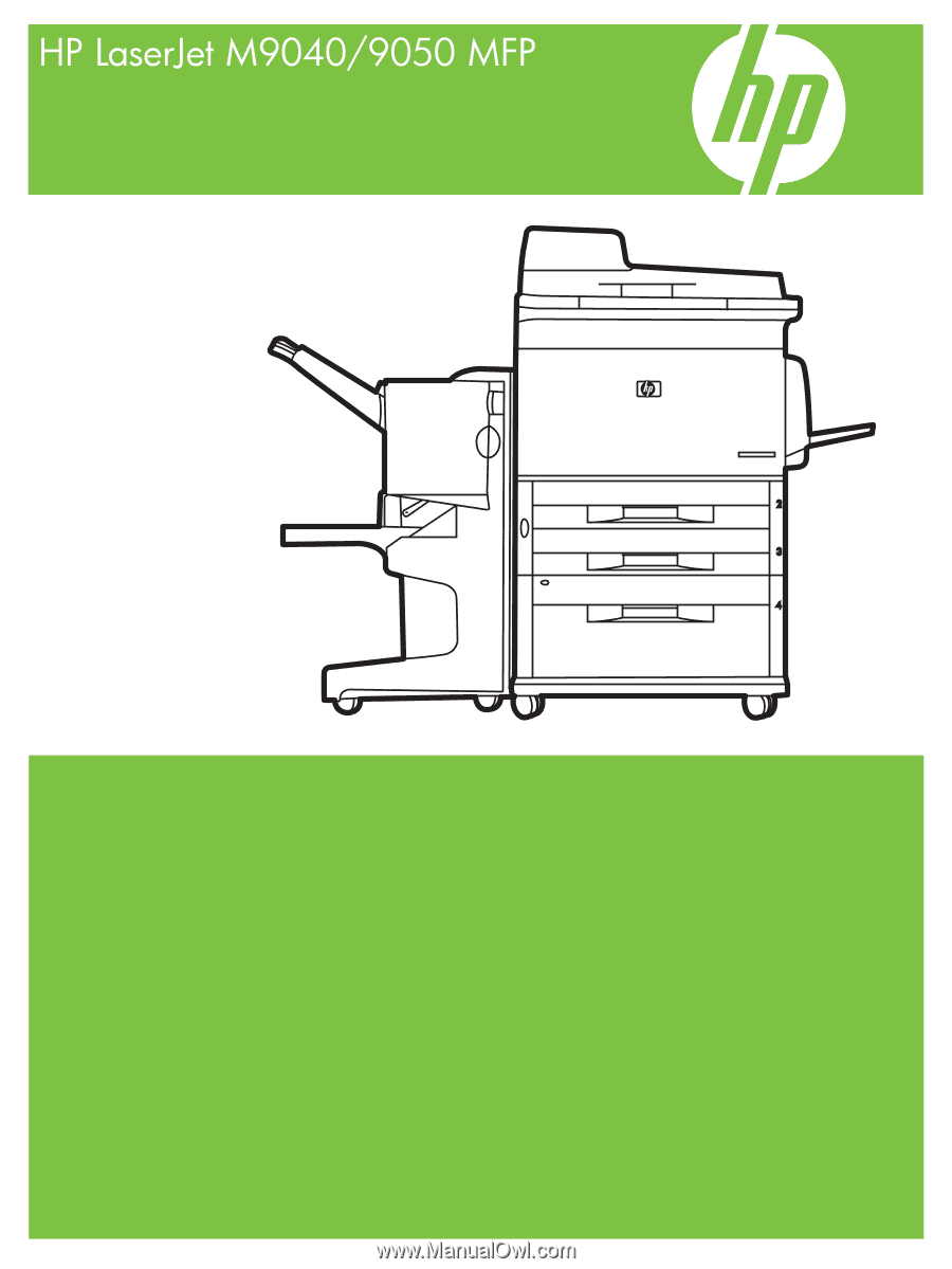
Service Manual