Intel BFCBASE Data Sheet - Page 103
Processor Thermal Features, 6.2.1 Thermal Monitor Features, 6.2.2 Thermal Monitor
 |
UPC - 735858197373
View all Intel BFCBASE manuals
Add to My Manuals
Save this manual to your list of manuals |
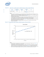
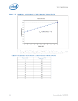
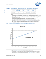
Page 103 highlights
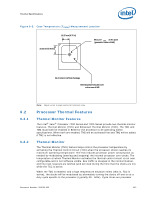
Thermal Specifications Figure 6-5. Case Temperature (TCASE) Measurement Location 19.25 mm [0.76 in] 19.25 mm [0.76 in] Measure T CASE at this point (geometric center of IHS) 53.34 mm FC-mPGA6 Package Thermal grease should cover entire area of IHS 6.2 6.2.1 6.2.2 Note: Figure is not to scale and is for reference only. Processor Thermal Features Thermal Monitor Features The Intel® Xeon® Processor 7200 Series and 7300 Series provide two thermal monitor features, Thermal Monitor (TM1) and Enhanced Thermal Monitor (TM2). The TM1 and TM2 must both be enabled in BIOS for the processor to be operating within specifications. When both are enabled, TM2 will be activated first and TM1 will be added if TM2 is not effective. Thermal Monitor The Thermal Monitor (TM1) feature helps control the processor temperature by activating the Thermal Control Circuit (TCC) when the processor silicon reaches its maximum operating temperature. The TCC reduces processor power consumption as needed by modulating (starting and stopping) the internal processor core clocks. The temperature at which Thermal Monitor activates the thermal control circuit is not user configurable and is not software visible. Bus traffic is snooped in the normal manner, and interrupt requests are latched (and serviced during the time that the clocks are on) while the TCC is active. When the TM1 is enabled, and a high temperature situation exists (that is, TCC is active), the clocks will be modulated by alternately turning the clocks off and on at a duty cycle specific to the processor (typically 30 - 50%). Cycle times are processor Document Number: 318080-002 103
-
 1
1 -
2
-
3
-
4
-
5
-
6
-
7
-
8
-
9
-
10
-
11
-
12
-
13
-
14
-
15
-
16
-
17
-
18
-
19
-
20
-
21
-
22
-
23
-
24
-
25
-
26
-
27
-
28
-
29
-
30
-
31
-
32
-
33
-
34
-
35
-
36
-
37
-
38
-
39
-
40
-
41
-
42
-
43
-
44
-
45
-
46
-
47
-
48
-
49
-
50
-
51
-
52
-
53
-
54
-
55
-
56
-
57
-
58
-
59
-
60
-
61
-
62
-
63
-
64
-
65
-
66
-
67
-
68
-
69
-
70
-
71
-
72
-
73
-
74
-
75
-
76
-
77
-
78
-
79
-
80
-
81
-
82
-
83
-
84
-
85
-
86
-
87
-
88
-
89
-
90
-
91
-
92
-
93
-
94
-
95
-
96
-
97
-
 98
98 -
 99
99 -
 100
100 -
 101
101 -
 102
102 -
 103
103 -
 104
104 -
 105
105 -
 106
106 -
 107
107 -
 108
108 -
109
-
110
-
111
-
112
-
113
-
114
-
115
-
116
-
117
-
118
-
119
-
120
-
121
-
122
-
123
-
124
-
125
-
126
-
127
-
128
-
129
-
130
-
131
-
132
-
133
-
134
-
135
-
136
-
137
-
138
-
139
-
140
-
141
-
142
 |
 |
