Intel BFCBASE Data Sheet - Page 3

Contents, Introduction, Electrical Specifications, Pin Listing, Signal Definitions - motherboard

Page 3 highlights

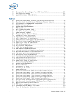
Contents 1 Introduction ...9 1.1 Terminology ...11 1.2 State of Data ...13 1.3 References ...13 2 Electrical Specifications 15 2.1 Front Side Bus and GTLREF 15 2.2 Decoupling Guidelines 15 2.2.1 VCC Decoupling 16 2.2.2 VTT Decoupling 16 2.2.3 Front Side Bus AGTL+ Decoupling 16 2.3 Front Side Bus Clock (BCLK[1:0]) and Processor Clocking 16 2.3.1 Front Side Bus Frequency Select Signals (BSEL[2:0 17 2.3.2 PLL Power Supply 17 2.4 Voltage Identification (VID 17 2.5 Reserved, Unused, or Test Signals 20 2.6 Front Side Bus Signal Groups 20 2.7 CMOS Asynchronous and Open Drain Asynchronous Signals 22 2.8 Test Access Port (TAP) Connection 22 2.9 Mixing Processors 23 2.10 Absolute Maximum and Minimum Ratings 23 2.11 Processor DC Specifications 24 2.11.1 Flexible Motherboard Guidelines (FMB 25 2.11.2 Platform Environmental Control Interface (PECI) DC Specifications 35 2.11.3 VCC Overshoot Specification 37 2.11.4 AGTL+ FSB Specifications 38 2.12 Front Side Bus AC Specifications 40 2.13 Processor AC Timing Waveforms 45 3 Mechanical Specifications 57 3.1 Package Mechanical Drawing 57 3.2 Processor Component Keepout Zones 60 3.3 Package Loading Specifications 66 3.4 Package Handling Guidelines 67 3.5 Package Insertion Specifications 67 3.6 Processor Mass Specifications 67 3.7 Processor Materials 67 3.8 Processor Markings 68 3.9 Processor Pin-Out Coordinates 69 4 Pin Listing ...71 4.1 Pin Assignments 71 4.1.1 Pin Listing by Pin Name 71 4.1.2 Pin Listing by Pin Number 79 5 Signal Definitions ...87 5.1 Signal Definitions 87 6 Thermal Specifications 95 6.1 Package Thermal Specifications 95 6.1.1 Thermal Specifications 95 6.1.2 Thermal Metrology 102 6.2 Processor Thermal Features 103 6.2.1 Thermal Monitor Features 103 6.2.2 Thermal Monitor 103 Document Number: 318080-002 3

  • 1
  • 2
  • 3
  • 4
  • 5
  • 6
  • 7
  • 8
  • 9
  • 10
  • 11
  • 12
  • 13
  • 14
  • 15
  • 16
  • 17
  • 18
  • 19
  • 20
  • 21
  • 22
  • 23
  • 24
  • 25
  • 26
  • 27
  • 28
  • 29
  • 30
  • 31
  • 32
  • 33
  • 34
  • 35
  • 36
  • 37
  • 38
  • 39
  • 40
  • 41
  • 42
  • 43
  • 44
  • 45
  • 46
  • 47
  • 48
  • 49
  • 50
  • 51
  • 52
  • 53
  • 54
  • 55
  • 56
  • 57
  • 58
  • 59
  • 60
  • 61
  • 62
  • 63
  • 64
  • 65
  • 66
  • 67
  • 68
  • 69
  • 70
  • 71
  • 72
  • 73
  • 74
  • 75
  • 76
  • 77
  • 78
  • 79
  • 80
  • 81
  • 82
  • 83
  • 84
  • 85
  • 86
  • 87
  • 88
  • 89
  • 90
  • 91
  • 92
  • 93
  • 94
  • 95
  • 96
  • 97
  • 98
  • 99
  • 100
  • 101
  • 102
  • 103
  • 104
  • 105
  • 106
  • 107
  • 108
  • 109
  • 110
  • 111
  • 112
  • 113
  • 114
  • 115
  • 116
  • 117
  • 118
  • 119
  • 120
  • 121
  • 122
  • 123
  • 124
  • 125
  • 126
  • 127
  • 128
  • 129
  • 130
  • 131
  • 132
  • 133
  • 134
  • 135
  • 136
  • 137
  • 138
  • 139
  • 140
  • 141
  • 142

Document Number: 318080-002
3
Contents
1
Introduction
..............................................................................................................
9
1.1
Terminology
.....................................................................................................
11
1.2
State of Data
....................................................................................................
13
1.3
References
.......................................................................................................
13
2
Electrical Specifications
...........................................................................................
15
2.1
Front Side Bus and GTLREF
................................................................................
15
2.2
Decoupling Guidelines
........................................................................................
15
2.2.1
VCC
Decoupling
......................................................................................
16
2.2.2
VTT
Decoupling
......................................................................................
16
2.2.3
Front Side Bus AGTL+ Decoupling
............................................................
16
2.3
Front Side Bus Clock (BCLK[1:0]) and Processor Clocking
.......................................
16
2.3.1
Front Side Bus Frequency Select Signals (BSEL[2:0])
..................................
17
2.3.2
PLL Power Supply
...................................................................................
17
2.4
Voltage Identification (VID)
................................................................................
17
2.5
Reserved, Unused, or Test Signals
.......................................................................
20
2.6
Front Side Bus Signal Groups
..............................................................................
20
2.7
CMOS Asynchronous and Open Drain Asynchronous Signals
....................................
22
2.8
Test Access Port (TAP) Connection
.......................................................................
22
2.9
Mixing Processors
..............................................................................................
23
2.10
Absolute Maximum and Minimum Ratings
.............................................................
23
2.11
Processor DC Specifications
................................................................................
24
2.11.1
Flexible Motherboard Guidelines (FMB)
......................................................
25
2.11.2
Platform Environmental Control Interface (PECI) DC Specifications
................
35
2.11.3
VCC Overshoot Specification
....................................................................
37
2.11.4
AGTL+ FSB Specifications
........................................................................
38
2.12
Front Side Bus AC Specifications
.........................................................................
40
2.13
Processor AC Timing Waveforms
.........................................................................
45
3
Mechanical Specifications
........................................................................................
57
3.1
Package Mechanical Drawing
...............................................................................
57
3.2
Processor Component Keepout Zones
...................................................................
60
3.3
Package Loading Specifications
...........................................................................
66
3.4
Package Handling Guidelines
...............................................................................
67
3.5
Package Insertion Specifications
..........................................................................
67
3.6
Processor Mass Specifications
.............................................................................
67
3.7
Processor Materials
............................................................................................
67
3.8
Processor Markings
............................................................................................
68
3.9
Processor Pin-Out Coordinates
............................................................................
69
4
Pin Listing
...............................................................................................................
71
4.1
Pin Assignments
................................................................................................
71
4.1.1
Pin Listing by Pin Name
...........................................................................
71
4.1.2
Pin Listing by Pin Number
........................................................................
79
5
Signal Definitions
....................................................................................................
87
5.1
Signal Definitions
. .............................................................................................
87
6
Thermal Specifications
............................................................................................
95
6.1
Package Thermal Specifications
...........................................................................
95
6.1.1
Thermal Specifications
............................................................................
95
6.1.2
Thermal Metrology
...............................................................................
102
6.2
Processor Thermal Features
..............................................................................
103
6.2.1
Thermal Monitor Features
......................................................................
103
6.2.2
Thermal Monitor
...................................................................................
103