Intel BFCBASE Data Sheet - Page 108
PECI Specifications
 |
UPC - 735858197373
View all Intel BFCBASE manuals
Add to My Manuals
Save this manual to your list of manuals |
Page 108 highlights
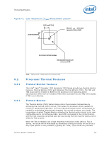
Thermal Specifications Figure 6-8. Conceptual Fan Control Diagram For a PECI-Based Platform Fan Speed (RPM) Min TCONTROL Setting Max PECI = -10 TCC Activation Temperature PECI = 0 PECI = -20 Temperature (not intended to depict actual implementation) 6.3.1.2 6.3.2 6.3.2.1 Processor Thermal Data Sample Rate and Filtering The DTS (Digital Thermal Sensors) provide an improved capability to monitor device hot spots, which inherently leads to more varying temperature readings over short time intervals. The DTS sample interval range can be modified, and a data filtering algorithm can be activated to help moderate this. The DTS sample interval range is 82 us (default) to 20 ms (max). This value can be set in BIOS. To reduce the sample rate requirements on PECI and improve thermal data stability vs. time the processor DTS also implements an averaging algorithm that filters the incoming data. This is an alpha-beta filter with coefficients of 0.5, and is expressed mathematically as: Current_filtered_temp = (Previous_filtered_temp / 2) + (new_sensor_temp / 2). This filtering algorithm is fixed and cannot be changed. It is on by default and can be turned off in BIOS. Host controllers should utilize the min/max sample times to determine the appropriate sample rate based on the controller's fan control algorithm and targeted response rate. The key items to take into account when settling on a fan control algorithm are the DTS sample rate, whether the temperature filter is enabled, how often the PECI host will poll the processor for temperature data, and the rate at which fan speed is changed. Depending on the designer's specific requirements the DTS sample rate and alpha-beta filter may have no effect on the fan control algorithm. PECI Specifications PECI Device Address The Intel® Xeon® Processor 7200 Series and 7300 Series obtains its PECI address based on the processor APIC ID[4:2] at power on. APIC ID[4:3] is also known as Cluster ID[1:0] and APIC ID[2] is also known as Agent ID[1]. Cluster ID[1:0] is set by the chipset driven power-on configuration (POC) signals A[12:11]#. Table 6-9 shows how the Agent ID is generated for each of the die based on the BREQ# signals asserted during power on for the Intel® Xeon® Processor 7200 Series and 7300 Series. 108 Document Number: 318080-002
-
 1
1 -
2
-
3
-
4
-
5
-
6
-
7
-
8
-
9
-
10
-
11
-
12
-
13
-
14
-
15
-
16
-
17
-
18
-
19
-
20
-
21
-
22
-
23
-
24
-
25
-
26
-
27
-
28
-
29
-
30
-
31
-
32
-
33
-
34
-
35
-
36
-
37
-
38
-
39
-
40
-
41
-
42
-
43
-
44
-
45
-
46
-
47
-
48
-
49
-
50
-
51
-
52
-
53
-
54
-
55
-
56
-
57
-
58
-
59
-
60
-
61
-
62
-
63
-
64
-
65
-
66
-
67
-
68
-
69
-
70
-
71
-
72
-
73
-
74
-
75
-
76
-
77
-
78
-
79
-
80
-
81
-
82
-
83
-
84
-
85
-
86
-
87
-
88
-
89
-
90
-
91
-
92
-
93
-
94
-
95
-
96
-
97
-
98
-
99
-
100
-
101
-
102
-
 103
103 -
 104
104 -
 105
105 -
 106
106 -
 107
107 -
 108
108 -
 109
109 -
 110
110 -
 111
111 -
 112
112 -
 113
113 -
114
-
115
-
116
-
117
-
118
-
119
-
120
-
121
-
122
-
123
-
124
-
125
-
126
-
127
-
128
-
129
-
130
-
131
-
132
-
133
-
134
-
135
-
136
-
137
-
138
-
139
-
140
-
141
-
142
 |
 |
