Intel BFCBASE Data Sheet - Page 107
Platform Environment Control Interface (PECI), 6.3.1 Introduction, PECI Topology
 |
UPC - 735858197373
View all Intel BFCBASE manuals
Add to My Manuals
Save this manual to your list of manuals |
Page 107 highlights
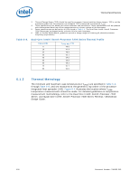
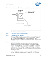
Thermal Specifications 6.3 Platform Environment Control Interface (PECI) 6.3.1 Introduction PECI offers an interface for thermal monitoring of Intel processor and chipset components. It uses a single wire, thus alleviating routing congestion issues. Figure 6-7 shows an example of the PECI topology in a system with Intel® Xeon® Processor 7200 Series and 7300 Series. PECI uses CRC checking on the host side to ensure reliable transfers between the host and client devices. Also, data transfer speeds across the PECI interface are negotiable within a wide range (2 Kbps to 2 Mbps). The PECI interface on Intel® Xeon® Processor 7200 Series and 7300 Series is disabled by default and must be enabled through BIOS. Figure 6-7. PECI Topology 6.3.1.1 PECI Host C o n tro lle r C28 C28 C28 C28 0 x 3 D o m ain 0 0 0 x 3 D o m ain 1 0 0 x 3 D o m ain 0 2 0 x 3 D o m ain 1 2 0 x 3 D o m ain 0 1 0 x 3 D o m ain 1 1 0 x 3 D o m ain 0 3 0 x 3 D o m ain 1 3 Socket 0 Cluster ID[1:0] = 0 Socket 1 Cluster ID[1:0] = 1 Socket 2 Cluster ID[1:0] = 2 Socket 3 Cluster ID[1:0] = 3 Note: The power-on configuration (POC) settings of third party chipsets may produce different PECI addresses than those shown in Figure 6-7. Thermal designers should consult their third party chipset designers for the correct PECI addresses. TCONTROL and Tcc Activation on PECI-Based Systems Fan speed control solutions based on PECI utilize a TCONTROL value stored in the processor IA32_TEMPERATURE_TARGET MSR. This MSR uses the same offset temperature format as PECI, though it contains no sign bit. Thermal management devices should infer the TCONTROL value as negative. Thermal management algorithms should utilize the relative temperature value delivered over PECI in conjunction with the MSR value to control or optimize fan speeds. Figure 6-8 shows a conceptual fan control diagram using PECI temperatures. Document Number: 318080-002 107
-
 1
1 -
2
-
3
-
4
-
5
-
6
-
7
-
8
-
9
-
10
-
11
-
12
-
13
-
14
-
15
-
16
-
17
-
18
-
19
-
20
-
21
-
22
-
23
-
24
-
25
-
26
-
27
-
28
-
29
-
30
-
31
-
32
-
33
-
34
-
35
-
36
-
37
-
38
-
39
-
40
-
41
-
42
-
43
-
44
-
45
-
46
-
47
-
48
-
49
-
50
-
51
-
52
-
53
-
54
-
55
-
56
-
57
-
58
-
59
-
60
-
61
-
62
-
63
-
64
-
65
-
66
-
67
-
68
-
69
-
70
-
71
-
72
-
73
-
74
-
75
-
76
-
77
-
78
-
79
-
80
-
81
-
82
-
83
-
84
-
85
-
86
-
87
-
88
-
89
-
90
-
91
-
92
-
93
-
94
-
95
-
96
-
97
-
98
-
99
-
100
-
101
-
 102
102 -
 103
103 -
 104
104 -
 105
105 -
 106
106 -
 107
107 -
 108
108 -
 109
109 -
 110
110 -
 111
111 -
 112
112 -
113
-
114
-
115
-
116
-
117
-
118
-
119
-
120
-
121
-
122
-
123
-
124
-
125
-
126
-
127
-
128
-
129
-
130
-
131
-
132
-
133
-
134
-
135
-
136
-
137
-
138
-
139
-
140
-
141
-
142
 |
 |
