Intel BFCBASE Data Sheet - Page 104
Thermal Monitor 2, Dual-Core Intel® Xeon® Processor 7200 Series
 |
UPC - 735858197373
View all Intel BFCBASE manuals
Add to My Manuals
Save this manual to your list of manuals |
Page 104 highlights
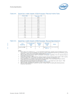
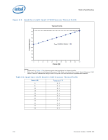
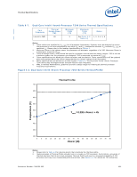
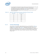
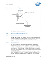
Thermal Specifications 6.2.3 Note: 104 speed dependent and will decrease as processor core frequencies increase. A small amount of hysteresis has been included to prevent rapid active/inactive transitions of the TCC when the processor temperature is near its maximum operating temperature. Once the temperature has dropped below the maximum operating temperature, and the hysteresis timer has expired, the TCC goes inactive and clock modulation ceases. With thermal solutions designed to each of the Intel® Xeon® Processor 7200 Series and 7300 Series Thermal Profile it is anticipated that the TCC would only be activated for very short periods of time when running the most power intensive applications. The processor performance impact due to these brief periods of TCC activation is expected to be so minor that it would be immeasurable. A thermal solution that is significantly under designed may not be capable of cooling the processor even when the TCC is active continuously Refer to the Dual-Core Intel® Xeon® Processor 7200 Series and Quad-Core Intel® Xeon® Processor 7300 Series Thermal / Mechanical Design Guide for information on designing a thermal solution. The duty cycle for the TCC, when activated by the TM1, is factory configured and cannot be modified. The TM1 does not require any additional hardware, software drivers, or interrupt handling routines. Thermal Monitor 2 The Intel® Xeon® Processor 7200 Series and 7300 Series adds supports for an Enhanced Thermal Monitor capability known as Thermal Monitor 2 (TM2). This mechanism provides an efficient means for limiting the processor temperature by reducing the power consumption within the processor. The Thermal Monitor or Enhanced Thermal Monitor must be enabled for the processor to be operating within specifications. TM2 requires support for dynamic VID transitions in the platform. Not all Intel® Xeon® Processor 7200 Series and 7300 Series are capable of supporting TM2. When Thermal Monitor 2 is enabled, and a high temperature situation is detected, the Thermal Control Circuit (TCC) will be activated for all processor cores. The TCC causes the processor to adjust its operating frequency (via the bus multiplier) and input voltage (via the VID signals). This combination of reduced frequency and VID results in a reduction to the processor power consumption. A processor enabled for Thermal Monitor 2 includes two operating points, each consisting of a specific operating frequency and voltage, which is identical for both processor dies. The first operating point represents the normal operating condition for the processor. Under this condition, the core-frequency-to-system-bus multiplier utilized by the processor is that contained in the CLOCK_FLEX_MAX MSR and the VID that is specified in Table 2-3. The second operating point consists of both a lower operating frequency and voltage. The lowest operating frequency is determined by the lowest supported bus ratio (1/6 for the Intel® Xeon® Processor 7200 Series and 7300 Series). When the TCC is activated, the processor automatically transitions to the new frequency. This transition occurs rapidly, on the order of 5 µs. During the frequency transition, the processor is unable to service any bus requests, and consequently, all bus traffic is blocked. Edgetriggered interrupts will be latched and kept pending until the processor resumes operation at the new frequency. Once the new operating frequency is engaged, the processor will transition to the new core operating voltage by issuing a new VID code to the voltage regulator. The voltage regulator must support dynamic VID steps in order to support Thermal Monitor 2. During the voltage change, it will be necessary to transition through multiple VID codes Document Number: 318080-002
-
 1
1 -
2
-
3
-
4
-
5
-
6
-
7
-
8
-
9
-
10
-
11
-
12
-
13
-
14
-
15
-
16
-
17
-
18
-
19
-
20
-
21
-
22
-
23
-
24
-
25
-
26
-
27
-
28
-
29
-
30
-
31
-
32
-
33
-
34
-
35
-
36
-
37
-
38
-
39
-
40
-
41
-
42
-
43
-
44
-
45
-
46
-
47
-
48
-
49
-
50
-
51
-
52
-
53
-
54
-
55
-
56
-
57
-
58
-
59
-
60
-
61
-
62
-
63
-
64
-
65
-
66
-
67
-
68
-
69
-
70
-
71
-
72
-
73
-
74
-
75
-
76
-
77
-
78
-
79
-
80
-
81
-
82
-
83
-
84
-
85
-
86
-
87
-
88
-
89
-
90
-
91
-
92
-
93
-
94
-
95
-
96
-
97
-
98
-
 99
99 -
 100
100 -
 101
101 -
 102
102 -
 103
103 -
 104
104 -
 105
105 -
 106
106 -
 107
107 -
 108
108 -
 109
109 -
110
-
111
-
112
-
113
-
114
-
115
-
116
-
117
-
118
-
119
-
120
-
121
-
122
-
123
-
124
-
125
-
126
-
127
-
128
-
129
-
130
-
131
-
132
-
133
-
134
-
135
-
136
-
137
-
138
-
139
-
140
-
141
-
142
 |
 |
