Intel BFCBASE Data Sheet - Page 90
Table 5-1., Signal Definitions Sheet 4 of 8, Description, Notes, Signals, Associated Strobes
 |
UPC - 735858197373
View all Intel BFCBASE manuals
Add to My Manuals
Save this manual to your list of manuals |
Page 90 highlights
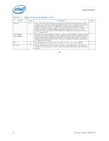
Signal Definitions Table 5-1. Signal Definitions (Sheet 4 of 8) Name DSTBN[3:0]# Type I/O Description Data strobe used to latch in D[63:0]#. Signals Associated Strobes D[15:0]#, DBI0# D[31:16]#, DBI1# D[47:32]#, DBI2# D[63:48]#, DBI3# DSTBN0# DSTBN1# DSTBN2# DSTBN3# DSTBP[3:0]# I/O Data strobe used to latch in D[63:0]#. Signals Associated Strobes D[15:0]#, DBI0# D[31:16]#, DBI1# D[47:32]#, DBI2# D[63:48]#, DBI3# DSTBP0# DSTBP1# DSTBP2# DSTBP3# Notes FERR#/PBE# FORCEPR# GTLREF_ADD_MID GTLREF_ADD_END GTLREF_DATA_MID GTLREF_DATA_END HIT# HITM# IERR# O FERR#/PBE# (floating-point error/pending break event) is a multiplexed signal and its meaning is qualified by STPCLK#. When STPCLK# is not asserted, FERR#/PBE# indicates a floating-point error and will be asserted when the processor detects an unmasked floating-point error. When STPCLK# is not asserted, FERR#/PBE# is similar to the ERROR# signal on the Intel 387 coprocessor, and is included for compatibility with systems using MS-DOS*-type floating-point error reporting. When STPCLK# is asserted, an assertion of FERR#/PBE# indicates that the processor has a pending break event waiting for service. The assertion of FERR#/PBE# indicates that the processor should be returned to the Normal state. For additional information on the pending break event functionality, including the identification of support of the feature and enable/disable information, refer to Vol. 3 of the IA_32 Intel ® Architecture Software Developer's Manual and the AP-485 Intel® Processor Identification and the CPUID Instruction application note. I The FORCEPR# (force power reduction) input can be used by the platform to cause the Intel® Xeon® Processor 7200 Series and 7300 Series to activate the Thermal Control Circuit (TCC). I GTLREF_ADD determines the signal reference level for AGTL+ address and common clock input pins. GTLREF_ADD is used by the AGTL+ receivers to determine if a signal is a logical 0 or a logical 1. Please refer to Table 2-17 and the appropriate platform design guidelines for additional details. I GTLREF_DATA determines the signal reference level for AGTL+ data input pins. GTLREF_DATA is used by the AGTL+ receivers to determine if a signal is a logical 0 or a logical 1. Please refer to Table 2-17 and the appropriate platform design guidelines for additional details. I/O HIT# (Snoop Hit) and HITM# (Hit Modified) convey transaction snoop operation I/O results. Any FSB agent may assert both HIT# and HITM# together to indicate that it requires a snoop stall, which can be continued by reasserting HIT# and HITM# together. O IERR# (Internal Error) is asserted by a processor as the result of an internal error. Assertion of IERR# is usually accompanied by a SHUTDOWN transaction on the processor FSB. This transaction may optionally be converted to an external error signal (e.g., NMI) by system core logic. The processor will keep IERR# asserted until the assertion of RESET#. This signal does not have on-die termination. 90 Document Number: 318080-002
-
 1
1 -
2
-
3
-
4
-
5
-
6
-
7
-
8
-
9
-
10
-
11
-
12
-
13
-
14
-
15
-
16
-
17
-
18
-
19
-
20
-
21
-
22
-
23
-
24
-
25
-
26
-
27
-
28
-
29
-
30
-
31
-
32
-
33
-
34
-
35
-
36
-
37
-
38
-
39
-
40
-
41
-
42
-
43
-
44
-
45
-
46
-
47
-
48
-
49
-
50
-
51
-
52
-
53
-
54
-
55
-
56
-
57
-
58
-
59
-
60
-
61
-
62
-
63
-
64
-
65
-
66
-
67
-
68
-
69
-
70
-
71
-
72
-
73
-
74
-
75
-
76
-
77
-
78
-
79
-
80
-
81
-
82
-
83
-
84
-
 85
85 -
 86
86 -
 87
87 -
 88
88 -
 89
89 -
 90
90 -
 91
91 -
 92
92 -
 93
93 -
 94
94 -
 95
95 -
96
-
97
-
98
-
99
-
100
-
101
-
102
-
103
-
104
-
105
-
106
-
107
-
108
-
109
-
110
-
111
-
112
-
113
-
114
-
115
-
116
-
117
-
118
-
119
-
120
-
121
-
122
-
123
-
124
-
125
-
126
-
127
-
128
-
129
-
130
-
131
-
132
-
133
-
134
-
135
-
136
-
137
-
138
-
139
-
140
-
141
-
142
 |
 |
