Intel BFCBASE Data Sheet - Page 96
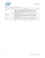
Table 6-1., Quad-Core Intel® Xeon® E7300 Processor Thermal Specifications
 |
UPC - 735858197373
View all Intel BFCBASE manuals
Add to My Manuals
Save this manual to your list of manuals |
Page 96 highlights
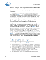
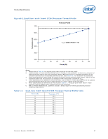
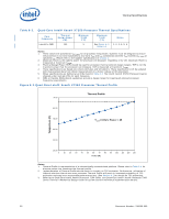
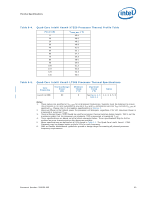
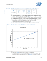
Thermal Specifications Additionally, utilization of a thermal solution that does not meet the Thermal Profile will violate the thermal specifications and may result in permanent damage to the processor. Refer to the Dual-Core Intel® Xeon® Processor 7200 Series and QuadCore Intel® Xeon® Processor 7300 Series Thermal / Mechanical Design Guide for details on system thermal solution design, thermal profiles and environmental considerations. For the Quad-Core Intel® Xeon® X7350 Processor, Intel has developed a thermal profile which must be met to ensure adherence to Intel reliability requirements. The Thermal Profile (see Figure 6-2; Table 6-4) is representative of a volumetrically unconstrained thermal solution (that is, industry enabled 2U heatsink). In this scenario, it is expected that the Thermal Control Circuit (TCC) would only be activated for very brief periods of time when running the most power intensive applications. Intel has developed the thermal profile to allow customers to choose the thermal solution and environmental parameters that best suit their platform implementation. Refer to the Dual-Core Intel® Xeon® Processor 7200 Series and Quad-Core Intel® Xeon® Processor 7300 Series Thermal / Mechanical Design Guide for details on system thermal solution design, thermal profiles and environmental considerations. The upper point of the thermal profile consists of the Thermal Design Power (TDP) and the associated TCASE value. It should be noted that the upper point associated with Quad-Core Intel® Xeon® X7350 Processor Thermal Profile (x = TDP and y = TCASE_MAX P @ TDP) represents a thermal solution design point. In actuality the processor case temperature will not reach this value due to TCC activation (see Figure 6-2 for QuadCore Intel® Xeon® X7350 Processor). Analysis indicates that real applications are unlikely to cause the processor to consume maximum power dissipation for sustained time periods. Intel recommends that complete thermal solution designs target the Thermal Design Power (TDP) instead of the maximum processor power consumption. The Thermal Monitor feature is intended to help protect the processor in the event that an application exceeds the TDP recommendation for a sustained time period. For more details on this feature, refer to Section 6.2. To ensure maximum flexibility for future requirements, systems should be designed to the Flexible Motherboard (FMB) guidelines, even if a processor with lower power dissipation is currently planned. Thermal Monitor and Thermal Monitor 2 feature must be enabled for the processor to remain within its specifications. Table 6-1. Quad-Core Intel® Xeon® E7300 Processor Thermal Specifications Core Frequency Launch to FMB Thermal Design Power (W) 80 Minimum TCASE (°C) 5 Maximum TCASE (°C) Notes See Figure 6-1; 1, 2, 3, 4, 5, 6 Table 6-2; Notes: 1. These values are specified at VCC_MAX for all processor frequencies. Systems must be designed to ensure the processor is not to be subjected to any static VCC and ICC combination wherein VCC exceeds VCC_MAX at specified ICC. Please refer to the loadline specifications in Section 2. 2. Maximum Power is the highest power the processor will dissipate, regardless of its VID. Maximum Power is measured at maximum TCASE. 3. Thermal Design Power (TDP) should be used for processor thermal solution design targets. TDP is not the maximum power that the processor can dissipate. TDP is measured at maximum TCASE. 4. These specifications are based on pre-silicon estimates and simulations. These specifications will be updated with characterized data from silicon measurements in a future release of this document. 5. Power specifications are defined at all VIDs found in Table 2-3. The Quad-Core Intel® Xeon® E7300 Processor may be shipped under multiple VIDs for each frequency. 6. FMB, or Flexible Motherboard, guidelines provide a design target for meeting all planned processor frequency requirements. 96 Document Number: 318080-002
-
 1
1 -
2
-
3
-
4
-
5
-
6
-
7
-
8
-
9
-
10
-
11
-
12
-
13
-
14
-
15
-
16
-
17
-
18
-
19
-
20
-
21
-
22
-
23
-
24
-
25
-
26
-
27
-
28
-
29
-
30
-
31
-
32
-
33
-
34
-
35
-
36
-
37
-
38
-
39
-
40
-
41
-
42
-
43
-
44
-
45
-
46
-
47
-
48
-
49
-
50
-
51
-
52
-
53
-
54
-
55
-
56
-
57
-
58
-
59
-
60
-
61
-
62
-
63
-
64
-
65
-
66
-
67
-
68
-
69
-
70
-
71
-
72
-
73
-
74
-
75
-
76
-
77
-
78
-
79
-
80
-
81
-
82
-
83
-
84
-
85
-
86
-
87
-
88
-
89
-
90
-
 91
91 -
 92
92 -
 93
93 -
 94
94 -
 95
95 -
 96
96 -
 97
97 -
 98
98 -
 99
99 -
 100
100 -
 101
101 -
102
-
103
-
104
-
105
-
106
-
107
-
108
-
109
-
110
-
111
-
112
-
113
-
114
-
115
-
116
-
117
-
118
-
119
-
120
-
121
-
122
-
123
-
124
-
125
-
126
-
127
-
128
-
129
-
130
-
131
-
132
-
133
-
134
-
135
-
136
-
137
-
138
-
139
-
140
-
141
-
142
 |
 |
