Lexmark C540 Service Manual - Page 140
Removal procedures, Front cover assembly removal
 |
View all Lexmark C540 manuals
Add to My Manuals
Save this manual to your list of manuals |
Page 140 highlights
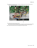
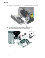
5025-2xx, 4xx Removal procedures CAUTION Remove the power cord from the electrical outlet before you connect or disconnect any cable or electronic board or assembly for personal safety and to prevent damage to the printer. Disconnect any connections between the printer and PCs/peripherals. Notes: • Remove the waste toner bottle, color toner cartridges, imaging unit, and media tray before removing other printer parts. The imaging unit should be carefully set on a clean, smooth, and flat surface. It should also be protected from light while out of the printer. • Unless otherwise stated, reinstall the parts in reverse order of removal. • When reinstalling a part held with several screws, start all screws before final tightening. • Some removal procedures require removing cable ties. You must replace cable ties during reassembly to avoid pinching wires, obstructing the paper path, or restricting mechanical movement. Front cover assembly removal See the front cover assembly on page 7-3 for the part number. 1. Open the front cover. 2. Remove the operator panel. See "Operator panel removal" on page 4-9. 3. Remove the right cover assembly. See "Right cover assembly removal" on page 4-10. 4. Remove the waste toner bottle. See "Waste toner bottle removal" on page 4-60. 5. Remove the four screws (A) from the cable cover, and remove the cable cover. 6. Remove the screw (B) from the back of the waste toner cartridge ground connector. A B 7. Remove the rear shield. See "Rear shield removal" on page 4-11. 4-2 Service Manual
-
 1
1 -
2
-
3
-
4
-
5
-
6
-
7
-
8
-
9
-
10
-
11
-
12
-
13
-
14
-
15
-
16
-
17
-
18
-
19
-
20
-
21
-
22
-
23
-
24
-
25
-
26
-
27
-
28
-
29
-
30
-
31
-
32
-
33
-
34
-
35
-
36
-
37
-
38
-
39
-
40
-
41
-
42
-
43
-
44
-
45
-
46
-
47
-
48
-
49
-
50
-
51
-
52
-
53
-
54
-
55
-
56
-
57
-
58
-
59
-
60
-
61
-
62
-
63
-
64
-
65
-
66
-
67
-
68
-
69
-
70
-
71
-
72
-
73
-
74
-
75
-
76
-
77
-
78
-
79
-
80
-
81
-
82
-
83
-
84
-
85
-
86
-
87
-
88
-
89
-
90
-
91
-
92
-
93
-
94
-
95
-
96
-
97
-
98
-
99
-
100
-
101
-
102
-
103
-
104
-
105
-
106
-
107
-
108
-
109
-
110
-
111
-
112
-
113
-
114
-
115
-
116
-
117
-
118
-
119
-
120
-
121
-
122
-
123
-
124
-
125
-
126
-
127
-
128
-
129
-
130
-
131
-
132
-
133
-
134
-
 135
135 -
 136
136 -
 137
137 -
 138
138 -
 139
139 -
 140
140 -
 141
141 -
 142
142 -
 143
143 -
 144
144 -
 145
145 -
146
-
147
-
148
-
149
-
150
-
151
-
152
-
153
-
154
-
155
-
156
-
157
-
158
-
159
-
160
-
161
-
162
-
163
-
164
-
165
-
166
-
167
-
168
-
169
-
170
-
171
-
172
-
173
-
174
-
175
-
176
-
177
-
178
-
179
-
180
-
181
-
182
-
183
-
184
-
185
-
186
-
187
-
188
-
189
-
190
-
191
-
192
-
193
-
194
-
195
-
196
-
197
-
198
-
199
-
200
-
201
-
202
-
203
-
204
-
205
-
206
-
207
-
208
-
209
-
210
-
211
-
212
-
213
-
214
-
215
-
216
-
217
-
218
-
219
-
220
-
221
-
222
-
223
-
224
-
225
-
226
-
227
-
228
-
229
-
230
-
231
-
232
-
233
-
234
-
235
-
236
 |
 |
