Lexmark C540 Service Manual - Page 191
Toner density sensor (TDS) removal-left or right sensor, Remove the ITU. See
 |
View all Lexmark C540 manuals
Add to My Manuals
Save this manual to your list of manuals |
Page 191 highlights
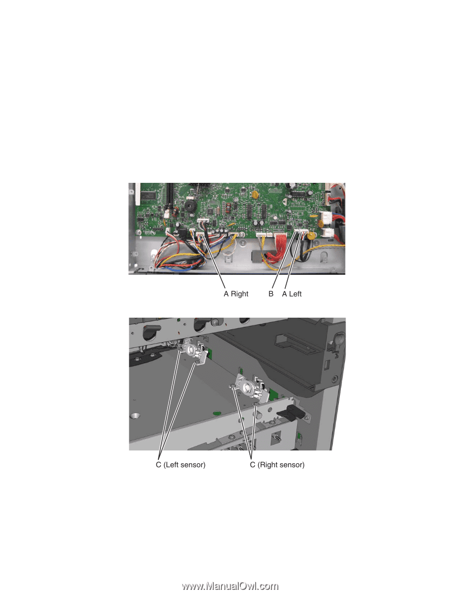
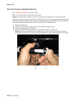
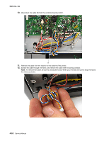
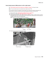
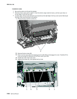
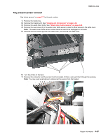
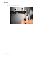
5025-2xx, 4xx Toner density sensor (TDS) removal-left or right sensor See "Toner density sensors, left or right (one in package)" on page 7-8 for the part number. Note: The toner density sensor is also called the toner patch sensor (TPS). The toner density sensors are the same, but the left sensor has a thermistor attached which needs to be removed when you install a new TDS on the left side. Reinstall the thermistor on the new TDS. 1. Remove the ITU. See "Image transfer unit (ITU) removal" on page 4-33. 2. Remove the rear shield. See "Rear shield removal" on page 4-11. 3. Disconnect the toner density sensor cable from JTDS1 connector (A Right) or JTDS2 connector (A Left) on the controller board. If you are removing the left toner density sensor, also disconnect the thermistor from JFUSES1 connector (B) on the controller board. Note: Observe the routing of the cable(s) for reinstallation. 4. Remove the two screws (C) securing each sensor. Repair information 4-53
-
 1
1 -
2
-
3
-
4
-
5
-
6
-
7
-
8
-
9
-
10
-
11
-
12
-
13
-
14
-
15
-
16
-
17
-
18
-
19
-
20
-
21
-
22
-
23
-
24
-
25
-
26
-
27
-
28
-
29
-
30
-
31
-
32
-
33
-
34
-
35
-
36
-
37
-
38
-
39
-
40
-
41
-
42
-
43
-
44
-
45
-
46
-
47
-
48
-
49
-
50
-
51
-
52
-
53
-
54
-
55
-
56
-
57
-
58
-
59
-
60
-
61
-
62
-
63
-
64
-
65
-
66
-
67
-
68
-
69
-
70
-
71
-
72
-
73
-
74
-
75
-
76
-
77
-
78
-
79
-
80
-
81
-
82
-
83
-
84
-
85
-
86
-
87
-
88
-
89
-
90
-
91
-
92
-
93
-
94
-
95
-
96
-
97
-
98
-
99
-
100
-
101
-
102
-
103
-
104
-
105
-
106
-
107
-
108
-
109
-
110
-
111
-
112
-
113
-
114
-
115
-
116
-
117
-
118
-
119
-
120
-
121
-
122
-
123
-
124
-
125
-
126
-
127
-
128
-
129
-
130
-
131
-
132
-
133
-
134
-
135
-
136
-
137
-
138
-
139
-
140
-
141
-
142
-
143
-
144
-
145
-
146
-
147
-
148
-
149
-
150
-
151
-
152
-
153
-
154
-
155
-
156
-
157
-
158
-
159
-
160
-
161
-
162
-
163
-
164
-
165
-
166
-
167
-
168
-
169
-
170
-
171
-
172
-
173
-
174
-
175
-
176
-
177
-
178
-
179
-
180
-
181
-
182
-
183
-
184
-
185
-
 186
186 -
 187
187 -
 188
188 -
 189
189 -
 190
190 -
 191
191 -
 192
192 -
 193
193 -
 194
194 -
 195
195 -
 196
196 -
197
-
198
-
199
-
200
-
201
-
202
-
203
-
204
-
205
-
206
-
207
-
208
-
209
-
210
-
211
-
212
-
213
-
214
-
215
-
216
-
217
-
218
-
219
-
220
-
221
-
222
-
223
-
224
-
225
-
226
-
227
-
228
-
229
-
230
-
231
-
232
-
233
-
234
-
235
-
236
 |
 |