Lexmark C540 Service Manual - Page 179
Right lower frame, Right cover assembly removal
 |
View all Lexmark C540 manuals
Add to My Manuals
Save this manual to your list of manuals |
Page 179 highlights
12. Remove the screw (G) above the frame. 5025-2xx, 4xx 13. Swing the left lower frame away from the printer, and remove. Right lower frame 1. Open the front cover. 2. Remove the right cover assembly. See "Right cover assembly removal" on page 4-10. 3. Remove the waste toner bottle. See "Waste toner bottle removal" on page 4-60. 4. Remove the imaging unit. See "Imaging unit (IU) removal" on page 4-35. 5. Remove the rear shield. See "Rear shield removal" on page 4-11. 6. Remove the rear screw (A) in the waste toner bottle sensor contact to allow access to the cable cover. Note: The waste toner bottle sensor contact does not need to be unplugged. Repair information 4-41
-
 1
1 -
2
-
3
-
4
-
5
-
6
-
7
-
8
-
9
-
10
-
11
-
12
-
13
-
14
-
15
-
16
-
17
-
18
-
19
-
20
-
21
-
22
-
23
-
24
-
25
-
26
-
27
-
28
-
29
-
30
-
31
-
32
-
33
-
34
-
35
-
36
-
37
-
38
-
39
-
40
-
41
-
42
-
43
-
44
-
45
-
46
-
47
-
48
-
49
-
50
-
51
-
52
-
53
-
54
-
55
-
56
-
57
-
58
-
59
-
60
-
61
-
62
-
63
-
64
-
65
-
66
-
67
-
68
-
69
-
70
-
71
-
72
-
73
-
74
-
75
-
76
-
77
-
78
-
79
-
80
-
81
-
82
-
83
-
84
-
85
-
86
-
87
-
88
-
89
-
90
-
91
-
92
-
93
-
94
-
95
-
96
-
97
-
98
-
99
-
100
-
101
-
102
-
103
-
104
-
105
-
106
-
107
-
108
-
109
-
110
-
111
-
112
-
113
-
114
-
115
-
116
-
117
-
118
-
119
-
120
-
121
-
122
-
123
-
124
-
125
-
126
-
127
-
128
-
129
-
130
-
131
-
132
-
133
-
134
-
135
-
136
-
137
-
138
-
139
-
140
-
141
-
142
-
143
-
144
-
145
-
146
-
147
-
148
-
149
-
150
-
151
-
152
-
153
-
154
-
155
-
156
-
157
-
158
-
159
-
160
-
161
-
162
-
163
-
164
-
165
-
166
-
167
-
168
-
169
-
170
-
171
-
172
-
173
-
 174
174 -
 175
175 -
 176
176 -
 177
177 -
 178
178 -
 179
179 -
 180
180 -
 181
181 -
 182
182 -
 183
183 -
 184
184 -
185
-
186
-
187
-
188
-
189
-
190
-
191
-
192
-
193
-
194
-
195
-
196
-
197
-
198
-
199
-
200
-
201
-
202
-
203
-
204
-
205
-
206
-
207
-
208
-
209
-
210
-
211
-
212
-
213
-
214
-
215
-
216
-
217
-
218
-
219
-
220
-
221
-
222
-
223
-
224
-
225
-
226
-
227
-
228
-
229
-
230
-
231
-
232
-
233
-
234
-
235
-
236
 |
 |
Repair information
4-41
5025-2xx, 4xx
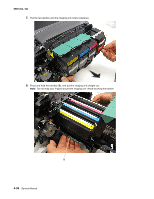
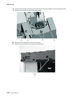
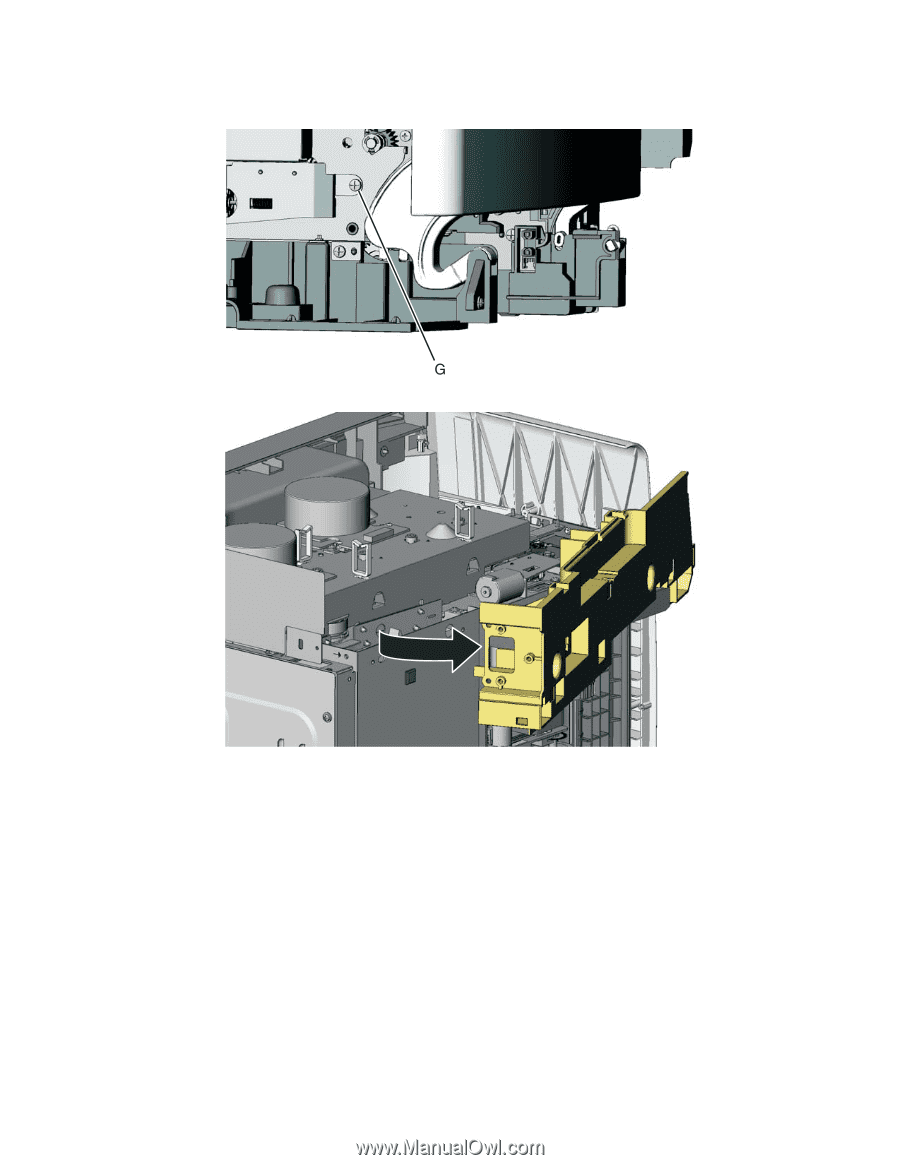
12.
Remove the screw (G) above the frame.
13.
Swing the left lower frame away from the printer, and remove.
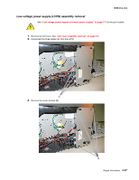
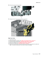
Right lower frame
1.
Open the front cover.
2.
Remove the right cover assembly. See
“Right cover assembly removal” on page 4-10
.
3.
Remove the waste toner bottle. See
“Waste toner bottle removal” on page 4-60
.
4.
Remove the imaging unit. See
“Imaging unit (IU) removal” on page 4-35
.
5.
Remove the rear shield. See
“Rear shield removal” on page 4-11
.
6.
Remove the rear screw (A) in the waste toner bottle sensor contact to allow access to the cable cover.
Note:
The waste toner bottle sensor contact does not need to be unplugged.