Lexmark C540 Service Manual - Page 62
Dead printer service check, 2xx, 4xx, Warning, Questions / actions, CAUTION, JLVPS1 exposed conductors
 |
View all Lexmark C540 manuals
Add to My Manuals
Save this manual to your list of manuals |
Page 62 highlights
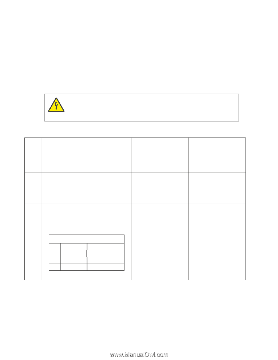
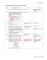
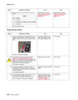
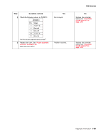
5025-2xx, 4xx Dead printer service check A dead printer is one which, when powered on from a known good electrical outlet, displays no indication of power to the printer by changes to the LCD, LED, or any movement of the fan or motors. If the printer appears dead but makes a beeping sound, check the operator panel. See "Operator panel display blank, five beeps" on page 2-37. If a 650-sheet duo drawer is installed, remove the option and check the base printer for correct operation. If the base printer operates correctly, replace the 650-sheet duo drawer. Warning: Observe all necessary ESD precautions when removing and handling the controller board or any installed option cards or assemblies. See "Handling ESD-sensitive parts" on page 4-1. CAUTION When you see this symbol, there is a danger from hazardous voltage in the area of the product where you are working. Unplug the product before you begin, or use caution if the product must receive power in order to perform the task. Remove any input paper-handling options from the printer. Step Questions / actions 1 Check the AC line voltage. Is the line voltage correct? 2 Is the AC line cord damaged? 3 Is the LVPS cable correctly connected at JLVPS1 on the controller board? Yes Go to step 2. Replace the line cord. Go to step 5. 4 Turn the printer off, and then on. Does the problem persist? 5 Warning: Damage to the printer is possible. Be careful to touch only one conductor at a time. Rest the probe against the connector to steady it. With the printer on, verify the following values at JLVPS1: JLVPS1 (exposed conductors) Pin Value 1 +5 V dc Pin Value 7 +24 V dc 3 +5 V dc 5 +5 V dc 9 +24 V dc 11 +24 V dc Are the values approximately correct? Go to step 5. Replace the controller board. See "Controller board removal" on page 4-19. No Inform the customer. Go to step 3. Reconnect the cable at JLVPS1, and then go to step 4. Problem resolved. Replace the LVPS. See "Low-voltage power supply (LVPS) assembly removal" on page 4-37. 2-28 Service Manual
-
 1
1 -
2
-
3
-
4
-
5
-
6
-
7
-
8
-
9
-
10
-
11
-
12
-
13
-
14
-
15
-
16
-
17
-
18
-
19
-
20
-
21
-
22
-
23
-
24
-
25
-
26
-
27
-
28
-
29
-
30
-
31
-
32
-
33
-
34
-
35
-
36
-
37
-
38
-
39
-
40
-
41
-
42
-
43
-
44
-
45
-
46
-
47
-
48
-
49
-
50
-
51
-
52
-
53
-
54
-
55
-
56
-
 57
57 -
 58
58 -
 59
59 -
 60
60 -
 61
61 -
 62
62 -
 63
63 -
 64
64 -
 65
65 -
 66
66 -
 67
67 -
68
-
69
-
70
-
71
-
72
-
73
-
74
-
75
-
76
-
77
-
78
-
79
-
80
-
81
-
82
-
83
-
84
-
85
-
86
-
87
-
88
-
89
-
90
-
91
-
92
-
93
-
94
-
95
-
96
-
97
-
98
-
99
-
100
-
101
-
102
-
103
-
104
-
105
-
106
-
107
-
108
-
109
-
110
-
111
-
112
-
113
-
114
-
115
-
116
-
117
-
118
-
119
-
120
-
121
-
122
-
123
-
124
-
125
-
126
-
127
-
128
-
129
-
130
-
131
-
132
-
133
-
134
-
135
-
136
-
137
-
138
-
139
-
140
-
141
-
142
-
143
-
144
-
145
-
146
-
147
-
148
-
149
-
150
-
151
-
152
-
153
-
154
-
155
-
156
-
157
-
158
-
159
-
160
-
161
-
162
-
163
-
164
-
165
-
166
-
167
-
168
-
169
-
170
-
171
-
172
-
173
-
174
-
175
-
176
-
177
-
178
-
179
-
180
-
181
-
182
-
183
-
184
-
185
-
186
-
187
-
188
-
189
-
190
-
191
-
192
-
193
-
194
-
195
-
196
-
197
-
198
-
199
-
200
-
201
-
202
-
203
-
204
-
205
-
206
-
207
-
208
-
209
-
210
-
211
-
212
-
213
-
214
-
215
-
216
-
217
-
218
-
219
-
220
-
221
-
222
-
223
-
224
-
225
-
226
-
227
-
228
-
229
-
230
-
231
-
232
-
233
-
234
-
235
-
236
 |
 |