Lexmark C540 Service Manual - Page 164
Fuser assembly removal, Right cover assembly removal
 |
View all Lexmark C540 manuals
Add to My Manuals
Save this manual to your list of manuals |
Page 164 highlights
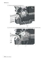
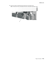
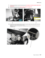
5025-2xx, 4xx Fuser assembly removal See "Fuser assembly" on page 7-5 for the part number. 1. Remove the right cover assembly. See "Right cover assembly removal" on page 4-10. 2. Remove the left cover. See "Left cover assembly removal" on page 4-6. 3. Disconnect the two-wire fuser cable (A) from the LVPS. 4. Position the fuser cable so that it can be pulled through from the front of the printer, and guide the cable through to the front. Warning: Be careful not to damage the cable by pulling too hard or cutting the cable insulation. 5. Remove the screw and grounding washer (B) on the right side of the frame. Note: Be careful not to lose the grounding washer. 6. Disconnect the thermistor cables (C). 4-26 Service Manual
-
 1
1 -
2
-
3
-
4
-
5
-
6
-
7
-
8
-
9
-
10
-
11
-
12
-
13
-
14
-
15
-
16
-
17
-
18
-
19
-
20
-
21
-
22
-
23
-
24
-
25
-
26
-
27
-
28
-
29
-
30
-
31
-
32
-
33
-
34
-
35
-
36
-
37
-
38
-
39
-
40
-
41
-
42
-
43
-
44
-
45
-
46
-
47
-
48
-
49
-
50
-
51
-
52
-
53
-
54
-
55
-
56
-
57
-
58
-
59
-
60
-
61
-
62
-
63
-
64
-
65
-
66
-
67
-
68
-
69
-
70
-
71
-
72
-
73
-
74
-
75
-
76
-
77
-
78
-
79
-
80
-
81
-
82
-
83
-
84
-
85
-
86
-
87
-
88
-
89
-
90
-
91
-
92
-
93
-
94
-
95
-
96
-
97
-
98
-
99
-
100
-
101
-
102
-
103
-
104
-
105
-
106
-
107
-
108
-
109
-
110
-
111
-
112
-
113
-
114
-
115
-
116
-
117
-
118
-
119
-
120
-
121
-
122
-
123
-
124
-
125
-
126
-
127
-
128
-
129
-
130
-
131
-
132
-
133
-
134
-
135
-
136
-
137
-
138
-
139
-
140
-
141
-
142
-
143
-
144
-
145
-
146
-
147
-
148
-
149
-
150
-
151
-
152
-
153
-
154
-
155
-
156
-
157
-
158
-
 159
159 -
 160
160 -
 161
161 -
 162
162 -
 163
163 -
 164
164 -
 165
165 -
 166
166 -
 167
167 -
 168
168 -
 169
169 -
170
-
171
-
172
-
173
-
174
-
175
-
176
-
177
-
178
-
179
-
180
-
181
-
182
-
183
-
184
-
185
-
186
-
187
-
188
-
189
-
190
-
191
-
192
-
193
-
194
-
195
-
196
-
197
-
198
-
199
-
200
-
201
-
202
-
203
-
204
-
205
-
206
-
207
-
208
-
209
-
210
-
211
-
212
-
213
-
214
-
215
-
216
-
217
-
218
-
219
-
220
-
221
-
222
-
223
-
224
-
225
-
226
-
227
-
228
-
229
-
230
-
231
-
232
-
233
-
234
-
235
-
236
 |
 |

4-26
Service Manual
5025-2xx, 4xx
Fuser assembly removal
See “Fuser assembly” on
page 7-5
for the part number.
1.
Remove the right cover assembly. See
“Right cover assembly removal” on page 4-10
.
2.
Remove the left cover. See
“Left cover assembly removal” on page 4-6
.
3.
Disconnect the two-wire fuser cable (A) from the LVPS.
4.
Position the fuser cable so that it can be pulled through from the front of the printer, and guide the cable
through to the front.
Warning:
Be careful not to damage the cable by pulling too hard or cutting the cable insulation.
5.
Remove the screw and grounding washer (B) on the right side of the frame.
Note:
Be careful not to lose the grounding washer.
6.
Disconnect the thermistor cables (C).