Lexmark C540 Service Manual - Page 187
Printhead removal, Printhead on Top cover assembly removal
 |
View all Lexmark C540 manuals
Add to My Manuals
Save this manual to your list of manuals |
Page 187 highlights
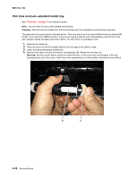
Installation notes: Install the new rubber tires with the surface texture turning in the direction as shown. 5025-2xx, 4xx Note: Feel each rubber surface to verify it turns properly in the direction shown. The smoother surface pushes the paper toward the front of the printer. Printhead removal See "Printhead" on page 7-5 for the part number. 1. Remove the top cover. See "Top cover assembly removal" on page 4-12. 2. Disconnect the cables from the controller board. Note: Be very careful disconnecting handling the ribbon cable. 3. Remove the toroid (A) from the ribbon cable. Note: Be sure to replace the toroid on the cable when you reinstall the printhead. Repair information 4-49
-
 1
1 -
2
-
3
-
4
-
5
-
6
-
7
-
8
-
9
-
10
-
11
-
12
-
13
-
14
-
15
-
16
-
17
-
18
-
19
-
20
-
21
-
22
-
23
-
24
-
25
-
26
-
27
-
28
-
29
-
30
-
31
-
32
-
33
-
34
-
35
-
36
-
37
-
38
-
39
-
40
-
41
-
42
-
43
-
44
-
45
-
46
-
47
-
48
-
49
-
50
-
51
-
52
-
53
-
54
-
55
-
56
-
57
-
58
-
59
-
60
-
61
-
62
-
63
-
64
-
65
-
66
-
67
-
68
-
69
-
70
-
71
-
72
-
73
-
74
-
75
-
76
-
77
-
78
-
79
-
80
-
81
-
82
-
83
-
84
-
85
-
86
-
87
-
88
-
89
-
90
-
91
-
92
-
93
-
94
-
95
-
96
-
97
-
98
-
99
-
100
-
101
-
102
-
103
-
104
-
105
-
106
-
107
-
108
-
109
-
110
-
111
-
112
-
113
-
114
-
115
-
116
-
117
-
118
-
119
-
120
-
121
-
122
-
123
-
124
-
125
-
126
-
127
-
128
-
129
-
130
-
131
-
132
-
133
-
134
-
135
-
136
-
137
-
138
-
139
-
140
-
141
-
142
-
143
-
144
-
145
-
146
-
147
-
148
-
149
-
150
-
151
-
152
-
153
-
154
-
155
-
156
-
157
-
158
-
159
-
160
-
161
-
162
-
163
-
164
-
165
-
166
-
167
-
168
-
169
-
170
-
171
-
172
-
173
-
174
-
175
-
176
-
177
-
178
-
179
-
180
-
181
-
 182
182 -
 183
183 -
 184
184 -
 185
185 -
 186
186 -
 187
187 -
 188
188 -
 189
189 -
 190
190 -
 191
191 -
 192
192 -
193
-
194
-
195
-
196
-
197
-
198
-
199
-
200
-
201
-
202
-
203
-
204
-
205
-
206
-
207
-
208
-
209
-
210
-
211
-
212
-
213
-
214
-
215
-
216
-
217
-
218
-
219
-
220
-
221
-
222
-
223
-
224
-
225
-
226
-
227
-
228
-
229
-
230
-
231
-
232
-
233
-
234
-
235
-
236
 |
 |
Repair information
4-49
5025-2xx, 4xx
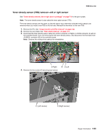
Installation notes:
Install the new rubber tires with the surface texture turning in the direction as shown.
Note:
Feel each rubber surface to verify it turns properly in the direction shown. The smoother surface pushes
the paper toward the front of the printer.
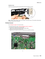
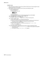
Printhead removal
See
“Printhead” on page 7-5
for the part number.
1.
Remove the top cover. See
“Top cover assembly removal” on page 4-12
.
2.
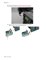
Disconnect the cables from the controller board.
Note:
Be very careful disconnecting handling the ribbon cable.
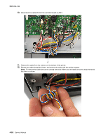
3.
Remove the toroid (A) from the ribbon cable.
Note:
Be sure to replace the toroid on the cable when you reinstall the printhead.