Lexmark C540 Service Manual - Page 80
Print quality-horizontal banding, 2xx, 4xx, Reports, Select, Print Defects, Questions / actions - itu removal
 |
View all Lexmark C540 manuals
Add to My Manuals
Save this manual to your list of manuals |
Page 80 highlights
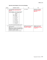
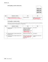
5025-2xx, 4xx Print quality-horizontal banding Print the Print Defect Page: 1. At the Ready prompt, press Menu ( ). 2. Select Reports, and press Select ( ). 3. Select Print Defects, and press Select ( ). Step Questions / actions Yes No 1 Measure the distance between repeating bands. Is the distance between bands either 34.6 or 94.2 mm? Replace the photoconductor unit. Remove the imaging unit and remove the original developer units, and then put them back into the new photoconductor unit, and reinstall the imaging unit. See "Imaging unit (IU) removal" on page 4-35. Go to step 2. 2 Does the distance measure 95 mm or 108 mm? Replace the fuser. See "Fuser assembly removal" on page 4-26. Go to step 3. 3 Does the distance measure 37.7, 55, or 78.5 mm? 4 Does the distance measure 43.9 mm or 45.5? Replace the ITU. See "Image transfer unit (ITU) removal" on page 4-33. Replace the developers that match the missing color (black, cyan, magenta, or yellow). See "Developer unit removal" on page 4-21. Go to step 4. Check the various rollers in the printer for debris. Print quality-horizontal line Either the photoconductor unit or one of the developer units that make up the imaging unit is defective. Remove and inspect the imaging unit. Replace the damaged part of the imaging unit. See "Imaging unit (IU) removal" on page 4-35. 2-46 Service Manual
-
 1
1 -
2
-
3
-
4
-
5
-
6
-
7
-
8
-
9
-
10
-
11
-
12
-
13
-
14
-
15
-
16
-
17
-
18
-
19
-
20
-
21
-
22
-
23
-
24
-
25
-
26
-
27
-
28
-
29
-
30
-
31
-
32
-
33
-
34
-
35
-
36
-
37
-
38
-
39
-
40
-
41
-
42
-
43
-
44
-
45
-
46
-
47
-
48
-
49
-
50
-
51
-
52
-
53
-
54
-
55
-
56
-
57
-
58
-
59
-
60
-
61
-
62
-
63
-
64
-
65
-
66
-
67
-
68
-
69
-
70
-
71
-
72
-
73
-
74
-
 75
75 -
 76
76 -
 77
77 -
 78
78 -
 79
79 -
 80
80 -
 81
81 -
 82
82 -
 83
83 -
 84
84 -
 85
85 -
86
-
87
-
88
-
89
-
90
-
91
-
92
-
93
-
94
-
95
-
96
-
97
-
98
-
99
-
100
-
101
-
102
-
103
-
104
-
105
-
106
-
107
-
108
-
109
-
110
-
111
-
112
-
113
-
114
-
115
-
116
-
117
-
118
-
119
-
120
-
121
-
122
-
123
-
124
-
125
-
126
-
127
-
128
-
129
-
130
-
131
-
132
-
133
-
134
-
135
-
136
-
137
-
138
-
139
-
140
-
141
-
142
-
143
-
144
-
145
-
146
-
147
-
148
-
149
-
150
-
151
-
152
-
153
-
154
-
155
-
156
-
157
-
158
-
159
-
160
-
161
-
162
-
163
-
164
-
165
-
166
-
167
-
168
-
169
-
170
-
171
-
172
-
173
-
174
-
175
-
176
-
177
-
178
-
179
-
180
-
181
-
182
-
183
-
184
-
185
-
186
-
187
-
188
-
189
-
190
-
191
-
192
-
193
-
194
-
195
-
196
-
197
-
198
-
199
-
200
-
201
-
202
-
203
-
204
-
205
-
206
-
207
-
208
-
209
-
210
-
211
-
212
-
213
-
214
-
215
-
216
-
217
-
218
-
219
-
220
-
221
-
222
-
223
-
224
-
225
-
226
-
227
-
228
-
229
-
230
-
231
-
232
-
233
-
234
-
235
-
236
 |
 |