Lexmark C540 Service Manual - Page 71
Operator panel display blank, five, 2xx, 4xx, Questions / actions, JOPP1, Value
 |
View all Lexmark C540 manuals
Add to My Manuals
Save this manual to your list of manuals |
Page 71 highlights
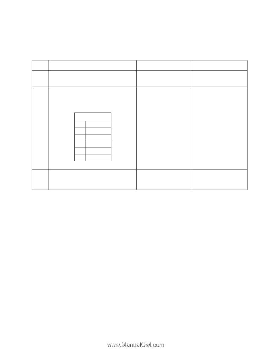
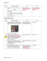
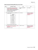
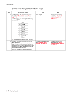
5025-2xx, 4xx Operator panel display blank, five beeps Service tip: The printer has detected a problem with the controller board, the operator panel assembly cable (part of the front cover assembly), or the operator panel assembly if POST does not complete. The printer emits five beeps, and sticks in a continuous pattern until the printer is turned off. Step Questions / actions 1 Is the operator panel assembly cable properly installed at controller board JOPP1 and at the operator panel assembly? 2 Turn the printer off, and remove the rear shield. See "Rear shield removal" on page 4-11. Turn the printer on, and verify the following values at JOPP1: JOPP1 Pin Value 2 +5 V dc 4 Ground 5 +5 V dc 6 +3.3 V dc 7 Ground Are the values approximately correct? 3 Check continuity of the operator panel assembly cable. Is there continuity? Yes Go to step 2. Go to step 3. Replace the operator panel assembly. See "Operator panel removal" on page 4-9. No Reinstall the cable. Replace the controller board. See "Controller board removal" on page 4-19. Replace the front cover assembly. See "Front cover assembly removal" on page 4-2. Diagnostic information 2-37
-
 1
1 -
2
-
3
-
4
-
5
-
6
-
7
-
8
-
9
-
10
-
11
-
12
-
13
-
14
-
15
-
16
-
17
-
18
-
19
-
20
-
21
-
22
-
23
-
24
-
25
-
26
-
27
-
28
-
29
-
30
-
31
-
32
-
33
-
34
-
35
-
36
-
37
-
38
-
39
-
40
-
41
-
42
-
43
-
44
-
45
-
46
-
47
-
48
-
49
-
50
-
51
-
52
-
53
-
54
-
55
-
56
-
57
-
58
-
59
-
60
-
61
-
62
-
63
-
64
-
65
-
 66
66 -
 67
67 -
 68
68 -
 69
69 -
 70
70 -
 71
71 -
 72
72 -
 73
73 -
 74
74 -
 75
75 -
 76
76 -
77
-
78
-
79
-
80
-
81
-
82
-
83
-
84
-
85
-
86
-
87
-
88
-
89
-
90
-
91
-
92
-
93
-
94
-
95
-
96
-
97
-
98
-
99
-
100
-
101
-
102
-
103
-
104
-
105
-
106
-
107
-
108
-
109
-
110
-
111
-
112
-
113
-
114
-
115
-
116
-
117
-
118
-
119
-
120
-
121
-
122
-
123
-
124
-
125
-
126
-
127
-
128
-
129
-
130
-
131
-
132
-
133
-
134
-
135
-
136
-
137
-
138
-
139
-
140
-
141
-
142
-
143
-
144
-
145
-
146
-
147
-
148
-
149
-
150
-
151
-
152
-
153
-
154
-
155
-
156
-
157
-
158
-
159
-
160
-
161
-
162
-
163
-
164
-
165
-
166
-
167
-
168
-
169
-
170
-
171
-
172
-
173
-
174
-
175
-
176
-
177
-
178
-
179
-
180
-
181
-
182
-
183
-
184
-
185
-
186
-
187
-
188
-
189
-
190
-
191
-
192
-
193
-
194
-
195
-
196
-
197
-
198
-
199
-
200
-
201
-
202
-
203
-
204
-
205
-
206
-
207
-
208
-
209
-
210
-
211
-
212
-
213
-
214
-
215
-
216
-
217
-
218
-
219
-
220
-
221
-
222
-
223
-
224
-
225
-
226
-
227
-
228
-
229
-
230
-
231
-
232
-
233
-
234
-
235
-
236
 |
 |