Lexmark C540 Service Manual - Page 141
Position the printer with the front cover overlapping the front edge of the table.
 |
View all Lexmark C540 manuals
Add to My Manuals
Save this manual to your list of manuals |
Page 141 highlights
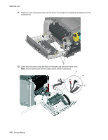
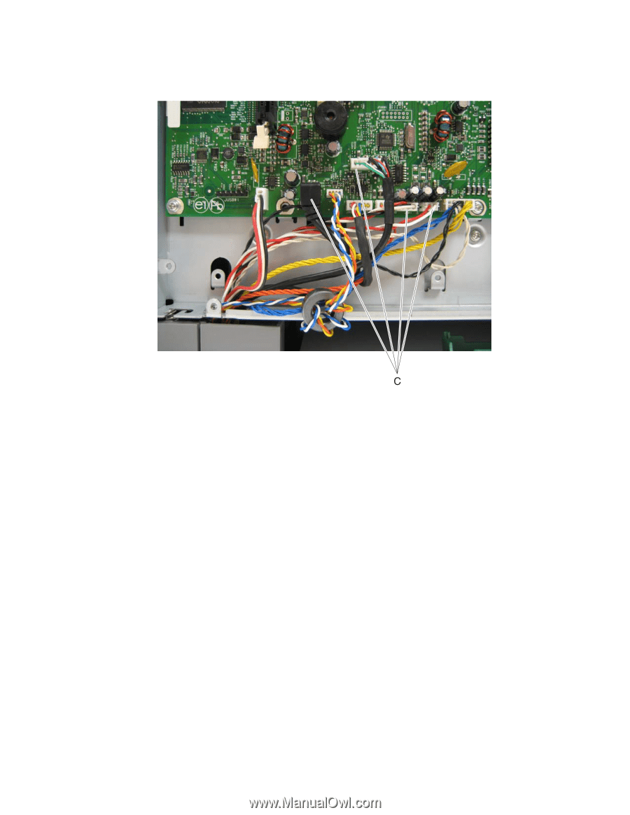
5025-2xx, 4xx 8. Disconnect the operator panel cable, the USB port (if installed) cable, and the front door open sensor cables from the controller board (C). 9. Pull the cables through the opening in the rear. Note: Remove the toroid by unwrapping the loops, and pulling the connector through the opening. When you re-install the cable, wrap five loops around the toroid before connecting to the controller board. 10. Position the printer with the front cover overlapping the front edge of the table. Repair information 4-3
-
 1
1 -
2
-
3
-
4
-
5
-
6
-
7
-
8
-
9
-
10
-
11
-
12
-
13
-
14
-
15
-
16
-
17
-
18
-
19
-
20
-
21
-
22
-
23
-
24
-
25
-
26
-
27
-
28
-
29
-
30
-
31
-
32
-
33
-
34
-
35
-
36
-
37
-
38
-
39
-
40
-
41
-
42
-
43
-
44
-
45
-
46
-
47
-
48
-
49
-
50
-
51
-
52
-
53
-
54
-
55
-
56
-
57
-
58
-
59
-
60
-
61
-
62
-
63
-
64
-
65
-
66
-
67
-
68
-
69
-
70
-
71
-
72
-
73
-
74
-
75
-
76
-
77
-
78
-
79
-
80
-
81
-
82
-
83
-
84
-
85
-
86
-
87
-
88
-
89
-
90
-
91
-
92
-
93
-
94
-
95
-
96
-
97
-
98
-
99
-
100
-
101
-
102
-
103
-
104
-
105
-
106
-
107
-
108
-
109
-
110
-
111
-
112
-
113
-
114
-
115
-
116
-
117
-
118
-
119
-
120
-
121
-
122
-
123
-
124
-
125
-
126
-
127
-
128
-
129
-
130
-
131
-
132
-
133
-
134
-
135
-
 136
136 -
 137
137 -
 138
138 -
 139
139 -
 140
140 -
 141
141 -
 142
142 -
 143
143 -
 144
144 -
 145
145 -
 146
146 -
147
-
148
-
149
-
150
-
151
-
152
-
153
-
154
-
155
-
156
-
157
-
158
-
159
-
160
-
161
-
162
-
163
-
164
-
165
-
166
-
167
-
168
-
169
-
170
-
171
-
172
-
173
-
174
-
175
-
176
-
177
-
178
-
179
-
180
-
181
-
182
-
183
-
184
-
185
-
186
-
187
-
188
-
189
-
190
-
191
-
192
-
193
-
194
-
195
-
196
-
197
-
198
-
199
-
200
-
201
-
202
-
203
-
204
-
205
-
206
-
207
-
208
-
209
-
210
-
211
-
212
-
213
-
214
-
215
-
216
-
217
-
218
-
219
-
220
-
221
-
222
-
223
-
224
-
225
-
226
-
227
-
228
-
229
-
230
-
231
-
232
-
233
-
234
-
235
-
236
 |
 |
Repair information
4-3
5025-2xx, 4xx
8.
Disconnect the operator panel cable, the USB port (if installed) cable, and the front door open sensor
cables from the controller board (C).
9.
Pull the cables through the opening in the rear.
Note:
Remove the toroid by unwrapping the loops, and pulling the connector through the opening. When
you re-install the cable, wrap five loops around the toroid before connecting to the controller board.
10.
Position the printer with the front cover overlapping the front edge of the table.