Lexmark C540 Service Manual - Page 69
Main drive gear assembly (EP drive) service check, 2xx, 4xx, Questions / actions, JCARTB1, Value
 |
View all Lexmark C540 manuals
Add to My Manuals
Save this manual to your list of manuals |
Page 69 highlights
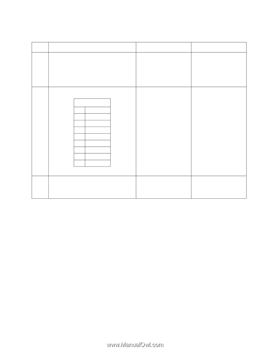
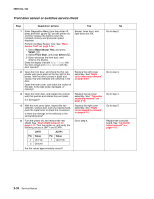
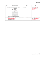
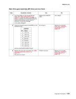
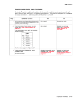
Main drive gear assembly (EP drive) service check Step Questions / actions Yes 1 Turn the printer off, and remove the rear shield. See "Rear shield removal" on page 4-11. Check the cable at JCARTB1 for proper connection to the controller board, the cable for pinch points, and the cable or connector for any other damage. Is the cable damaged? Replace the JCARTB1 cable. 2 Verify the following values at JCARTB1 on the controller board. JCARTB1 Pin Value 4 +24 V dc 6 +24 V dc 8 +24 V dc 9 Ground 12 Ground 13 +24 V dc 15 +24 V dc 17 +24 V dc Go to step 3. Are the values approximately correct? 3 Replace the main drive assembly. See "Main drive gear assembly removal" on page 4-45. Does the error clear? Problem resolved. 5025-2xx, 4xx No Go to step 2. Replace the controller board. See "Controller board removal" on page 4-19. Replace the controller board. See "Controller board removal" on page 4-19. Diagnostic information 2-35
-
 1
1 -
2
-
3
-
4
-
5
-
6
-
7
-
8
-
9
-
10
-
11
-
12
-
13
-
14
-
15
-
16
-
17
-
18
-
19
-
20
-
21
-
22
-
23
-
24
-
25
-
26
-
27
-
28
-
29
-
30
-
31
-
32
-
33
-
34
-
35
-
36
-
37
-
38
-
39
-
40
-
41
-
42
-
43
-
44
-
45
-
46
-
47
-
48
-
49
-
50
-
51
-
52
-
53
-
54
-
55
-
56
-
57
-
58
-
59
-
60
-
61
-
62
-
63
-
 64
64 -
 65
65 -
 66
66 -
 67
67 -
 68
68 -
 69
69 -
 70
70 -
 71
71 -
 72
72 -
 73
73 -
 74
74 -
75
-
76
-
77
-
78
-
79
-
80
-
81
-
82
-
83
-
84
-
85
-
86
-
87
-
88
-
89
-
90
-
91
-
92
-
93
-
94
-
95
-
96
-
97
-
98
-
99
-
100
-
101
-
102
-
103
-
104
-
105
-
106
-
107
-
108
-
109
-
110
-
111
-
112
-
113
-
114
-
115
-
116
-
117
-
118
-
119
-
120
-
121
-
122
-
123
-
124
-
125
-
126
-
127
-
128
-
129
-
130
-
131
-
132
-
133
-
134
-
135
-
136
-
137
-
138
-
139
-
140
-
141
-
142
-
143
-
144
-
145
-
146
-
147
-
148
-
149
-
150
-
151
-
152
-
153
-
154
-
155
-
156
-
157
-
158
-
159
-
160
-
161
-
162
-
163
-
164
-
165
-
166
-
167
-
168
-
169
-
170
-
171
-
172
-
173
-
174
-
175
-
176
-
177
-
178
-
179
-
180
-
181
-
182
-
183
-
184
-
185
-
186
-
187
-
188
-
189
-
190
-
191
-
192
-
193
-
194
-
195
-
196
-
197
-
198
-
199
-
200
-
201
-
202
-
203
-
204
-
205
-
206
-
207
-
208
-
209
-
210
-
211
-
212
-
213
-
214
-
215
-
216
-
217
-
218
-
219
-
220
-
221
-
222
-
223
-
224
-
225
-
226
-
227
-
228
-
229
-
230
-
231
-
232
-
233
-
234
-
235
-
236
 |
 |