Lexmark C540 Service Manual - Page 87
Transfer roll service check, Tray 1 sensor service check, 2xx, 4xx, Questions / actions, JHVPS1, Value
 |
View all Lexmark C540 manuals
Add to My Manuals
Save this manual to your list of manuals |
Page 87 highlights
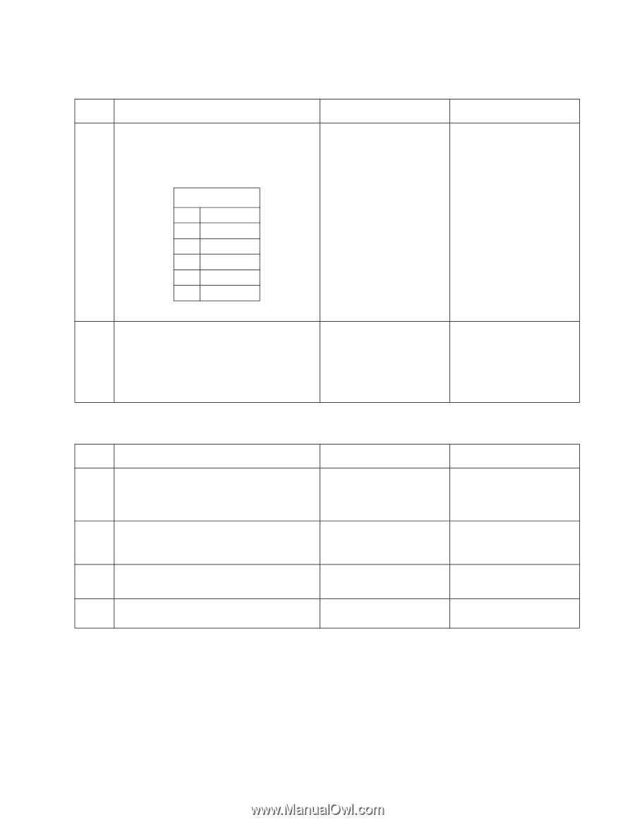
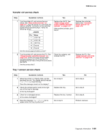
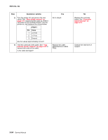
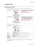
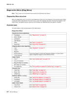
5025-2xx, 4xx Transfer roll service check Step Questions / actions Yes No 1 Turn the printer off, and remove the rear shield. See "Rear shield removal" on page 4-11. Turn the printer on, and check the cable at JHVPS1 connector on the controller board without disconnecting it. Verify the following values: JHVPS1 Pin Value 7 +3.3 V dc 11 +3.3 V dc 13 +24 V dc 14 Ground 16 Ground Are the values approximately correct? Replace the HVPS. See "High-voltage power supply (HVPS) assembly removal" on page 4-31. If the problem persists, go to step 2. Replace the controller board. See "Controller board removal" on page 4-19. 2 Turn the printer off, and remove the ITU. See "Image transfer unit (ITU) removal" on page 4-33. Check the three spring-loaded contacts between the HVPS and the ITU located at the left rear of the printer and above the HVPS. Are the contact dirty?. Clean the contacts, and reinstall the ITU. Replace the ITU. See "Image transfer unit (ITU) removal" on page 4-33. Tray 1 sensor service check Step Questions / actions 1 When the printer is in Ready state, pull the standard tray out. The display should indicate Tray 1 Missing. Insert the tray. Does the message remain on the display? 2 Check the vertical wall (or web) at the right rear of the tray for damage. Is the tray damaged? 3 Check for a dislodged sensor. Is the sensor dislodged? 4 Does the message Tray 1 Missing fail to appear when the tray is pulled out? Yes Go to step 2. Replace the tray. Replace the tray 1 sensor. Go to step 5. No Go to step 4. Go to step 3. Go to step 6. Problem resolved. Diagnostic information 2-53
-
 1
1 -
2
-
3
-
4
-
5
-
6
-
7
-
8
-
9
-
10
-
11
-
12
-
13
-
14
-
15
-
16
-
17
-
18
-
19
-
20
-
21
-
22
-
23
-
24
-
25
-
26
-
27
-
28
-
29
-
30
-
31
-
32
-
33
-
34
-
35
-
36
-
37
-
38
-
39
-
40
-
41
-
42
-
43
-
44
-
45
-
46
-
47
-
48
-
49
-
50
-
51
-
52
-
53
-
54
-
55
-
56
-
57
-
58
-
59
-
60
-
61
-
62
-
63
-
64
-
65
-
66
-
67
-
68
-
69
-
70
-
71
-
72
-
73
-
74
-
75
-
76
-
77
-
78
-
79
-
80
-
81
-
 82
82 -
 83
83 -
 84
84 -
 85
85 -
 86
86 -
 87
87 -
 88
88 -
 89
89 -
 90
90 -
 91
91 -
 92
92 -
93
-
94
-
95
-
96
-
97
-
98
-
99
-
100
-
101
-
102
-
103
-
104
-
105
-
106
-
107
-
108
-
109
-
110
-
111
-
112
-
113
-
114
-
115
-
116
-
117
-
118
-
119
-
120
-
121
-
122
-
123
-
124
-
125
-
126
-
127
-
128
-
129
-
130
-
131
-
132
-
133
-
134
-
135
-
136
-
137
-
138
-
139
-
140
-
141
-
142
-
143
-
144
-
145
-
146
-
147
-
148
-
149
-
150
-
151
-
152
-
153
-
154
-
155
-
156
-
157
-
158
-
159
-
160
-
161
-
162
-
163
-
164
-
165
-
166
-
167
-
168
-
169
-
170
-
171
-
172
-
173
-
174
-
175
-
176
-
177
-
178
-
179
-
180
-
181
-
182
-
183
-
184
-
185
-
186
-
187
-
188
-
189
-
190
-
191
-
192
-
193
-
194
-
195
-
196
-
197
-
198
-
199
-
200
-
201
-
202
-
203
-
204
-
205
-
206
-
207
-
208
-
209
-
210
-
211
-
212
-
213
-
214
-
215
-
216
-
217
-
218
-
219
-
220
-
221
-
222
-
223
-
224
-
225
-
226
-
227
-
228
-
229
-
230
-
231
-
232
-
233
-
234
-
235
-
236
 |
 |