Lexmark C540 Service Manual - Page 65
Fuser exit sensor service check, 2xx, 4xx, With front cover and toner door closed
 |
View all Lexmark C540 manuals
Add to My Manuals
Save this manual to your list of manuals |
Page 65 highlights
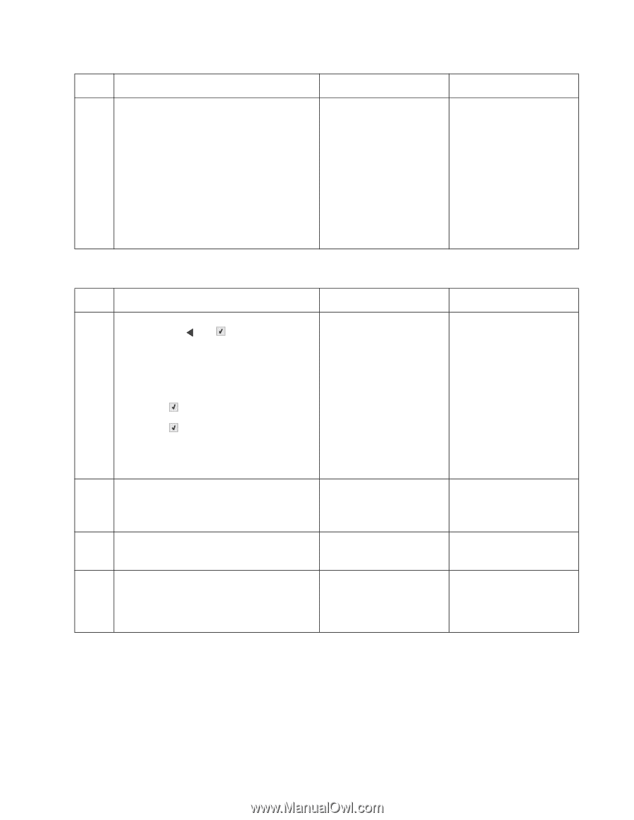
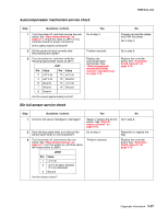
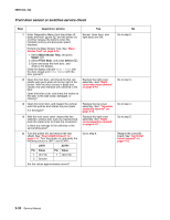
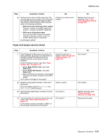
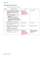
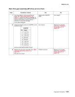
5025-2xx, 4xx Step Questions / actions Yes 6 Close the front cover and the toner door. Be Contact your next level of sure the right cover is in place. Turn the printer support. off, and then disconnect the cables at JINT1 and JCVR1. Test continuity at the connector under the following conditions: • With front cover and toner door closed: Test pin 1 and pin 3 at JINT1 cable end and pin 1 and pin 2 at JCVR1 cable end. • With one or both doors open: Pin 2 and 3 at JINT1 cable end should indicate continuity, but pins 1 and 2 at JCVR1 should have no continuity. Are the tests verified? Fuser exit sensor service check No Replace the front cover assembly. See "Front cover assembly removal" on page 4-2. Step Questions / actions Yes 1 Enter Diagnostics Menu (turn the printer off, press and hold and , turn the printer on, and then release the buttons when the installed memory and processor speed displays). Perform the Base Sensor Test. See "Base Sensor Test" on page 3-16. 1. Select Base Sensor Test, and press Select ( ). 2. Select Fuser Exit Sensor, and press Select ( ). 3. Open and close the front door, and inspect the fuser exit sensor located on the LVPS shield. Is the sensor dislodged or damaged? Correct the sensor, or replace it. See "Fuser exit sensor removal" on page 4-30. 2 Rotate the flag (paper diverter) in and out of the sensor. Does the display indicate Media Clear and Media Present with the cycle? 3 Does the flag rotate freely, but return to block the sensor? Sensor is good. Go to step 4. 4 Turn the printer off, and then remove the rear shield. See "Rear shield removal" on page 4-11. Is the cable correctly connected to JBIN1 on the controller board and to the sensor? Go to step 5. No Go to step 2. Go to step 3. Replace the fuser. See "Fuser assembly removal" on page 4-26. Reconnect the cable. Diagnostic information 2-31
-
 1
1 -
2
-
3
-
4
-
5
-
6
-
7
-
8
-
9
-
10
-
11
-
12
-
13
-
14
-
15
-
16
-
17
-
18
-
19
-
20
-
21
-
22
-
23
-
24
-
25
-
26
-
27
-
28
-
29
-
30
-
31
-
32
-
33
-
34
-
35
-
36
-
37
-
38
-
39
-
40
-
41
-
42
-
43
-
44
-
45
-
46
-
47
-
48
-
49
-
50
-
51
-
52
-
53
-
54
-
55
-
56
-
57
-
58
-
59
-
 60
60 -
 61
61 -
 62
62 -
 63
63 -
 64
64 -
 65
65 -
 66
66 -
 67
67 -
 68
68 -
 69
69 -
 70
70 -
71
-
72
-
73
-
74
-
75
-
76
-
77
-
78
-
79
-
80
-
81
-
82
-
83
-
84
-
85
-
86
-
87
-
88
-
89
-
90
-
91
-
92
-
93
-
94
-
95
-
96
-
97
-
98
-
99
-
100
-
101
-
102
-
103
-
104
-
105
-
106
-
107
-
108
-
109
-
110
-
111
-
112
-
113
-
114
-
115
-
116
-
117
-
118
-
119
-
120
-
121
-
122
-
123
-
124
-
125
-
126
-
127
-
128
-
129
-
130
-
131
-
132
-
133
-
134
-
135
-
136
-
137
-
138
-
139
-
140
-
141
-
142
-
143
-
144
-
145
-
146
-
147
-
148
-
149
-
150
-
151
-
152
-
153
-
154
-
155
-
156
-
157
-
158
-
159
-
160
-
161
-
162
-
163
-
164
-
165
-
166
-
167
-
168
-
169
-
170
-
171
-
172
-
173
-
174
-
175
-
176
-
177
-
178
-
179
-
180
-
181
-
182
-
183
-
184
-
185
-
186
-
187
-
188
-
189
-
190
-
191
-
192
-
193
-
194
-
195
-
196
-
197
-
198
-
199
-
200
-
201
-
202
-
203
-
204
-
205
-
206
-
207
-
208
-
209
-
210
-
211
-
212
-
213
-
214
-
215
-
216
-
217
-
218
-
219
-
220
-
221
-
222
-
223
-
224
-
225
-
226
-
227
-
228
-
229
-
230
-
231
-
232
-
233
-
234
-
235
-
236
 |
 |