Lexmark C540 Service Manual - Page 157
Controller board removal - c540n troubleshooting
 |
View all Lexmark C540 manuals
Add to My Manuals
Save this manual to your list of manuals |
Page 157 highlights
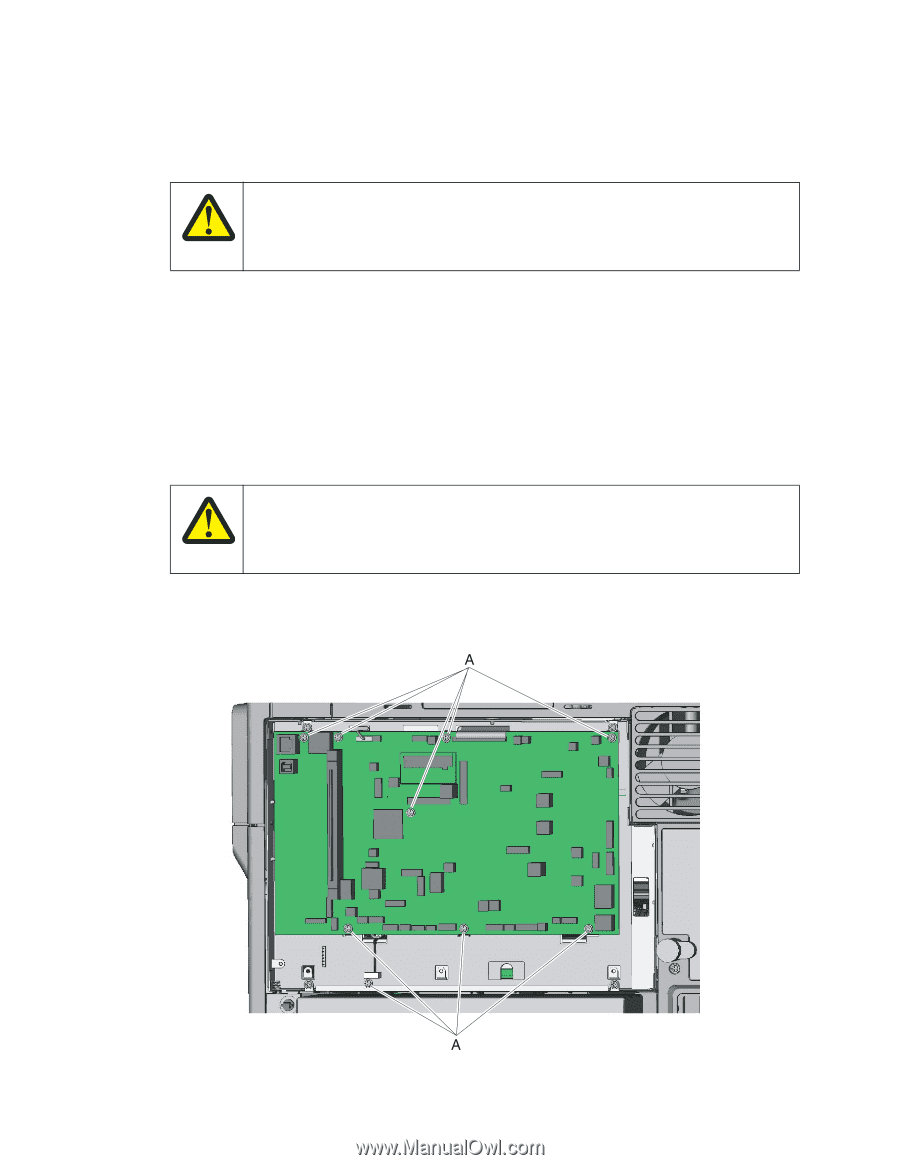
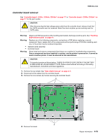
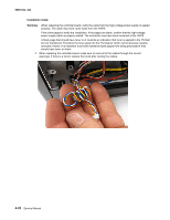
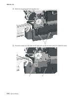
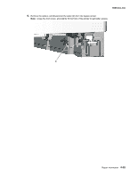
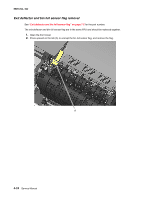
5025-2xx, 4xx Controller board removal See "Controller board-C544n, C544dn, C544dw" on page 7-7 or "Controller board-C540n, C543dn" on page 7-7 for the part number. CAUTION After disconnecting the high-voltage power cable from the controller board, always check that the HVPS connector was not loosened. Make this check anytime you are working near the HVPS cable. Warning: Observe all ESD precautions while handling electrostatic-discharge sensitive parts. See "Handling ESD-sensitive parts" on page 4-1. Warning: Replace one of the following components, and perform a POR before replacing a second component. Never replace both of the components without performing a POR after installing each one, or the printer may be rendered inoperable: • Operator panel assembly • Controller board Warning: Never install and remove components listed above as a method of troubleshooting components. Once a component has been installed in a printer, and the printer is powered on, it cannot be used in another printer. It must be returned to the manufacturer. CAUTION This product contains a lithium battery. THERE IS A RISK OF EXPLOSION IF THE BATTERY IS REPLACED BY AN INCORRECT TYPE. Discard used batteries according to the battery manufacturer's instructions and local regulations. 1. Remove the rear shield. See "Rear shield removal" on page 4-11. 2. Disconnect all the cables from the controller board. 3. Remove the nine screws (A) that are securing the controller board. 4. Remove the board. Repair information 4-19
-
 1
1 -
2
-
3
-
4
-
5
-
6
-
7
-
8
-
9
-
10
-
11
-
12
-
13
-
14
-
15
-
16
-
17
-
18
-
19
-
20
-
21
-
22
-
23
-
24
-
25
-
26
-
27
-
28
-
29
-
30
-
31
-
32
-
33
-
34
-
35
-
36
-
37
-
38
-
39
-
40
-
41
-
42
-
43
-
44
-
45
-
46
-
47
-
48
-
49
-
50
-
51
-
52
-
53
-
54
-
55
-
56
-
57
-
58
-
59
-
60
-
61
-
62
-
63
-
64
-
65
-
66
-
67
-
68
-
69
-
70
-
71
-
72
-
73
-
74
-
75
-
76
-
77
-
78
-
79
-
80
-
81
-
82
-
83
-
84
-
85
-
86
-
87
-
88
-
89
-
90
-
91
-
92
-
93
-
94
-
95
-
96
-
97
-
98
-
99
-
100
-
101
-
102
-
103
-
104
-
105
-
106
-
107
-
108
-
109
-
110
-
111
-
112
-
113
-
114
-
115
-
116
-
117
-
118
-
119
-
120
-
121
-
122
-
123
-
124
-
125
-
126
-
127
-
128
-
129
-
130
-
131
-
132
-
133
-
134
-
135
-
136
-
137
-
138
-
139
-
140
-
141
-
142
-
143
-
144
-
145
-
146
-
147
-
148
-
149
-
150
-
151
-
 152
152 -
 153
153 -
 154
154 -
 155
155 -
 156
156 -
 157
157 -
 158
158 -
 159
159 -
 160
160 -
 161
161 -
 162
162 -
163
-
164
-
165
-
166
-
167
-
168
-
169
-
170
-
171
-
172
-
173
-
174
-
175
-
176
-
177
-
178
-
179
-
180
-
181
-
182
-
183
-
184
-
185
-
186
-
187
-
188
-
189
-
190
-
191
-
192
-
193
-
194
-
195
-
196
-
197
-
198
-
199
-
200
-
201
-
202
-
203
-
204
-
205
-
206
-
207
-
208
-
209
-
210
-
211
-
212
-
213
-
214
-
215
-
216
-
217
-
218
-
219
-
220
-
221
-
222
-
223
-
224
-
225
-
226
-
227
-
228
-
229
-
230
-
231
-
232
-
233
-
234
-
235
-
236
 |
 |