Lexmark C540 Service Manual - Page 167
Fuser drive motor assembly removal, Fuser drive motor assembly
 |
View all Lexmark C540 manuals
Add to My Manuals
Save this manual to your list of manuals |
Page 167 highlights
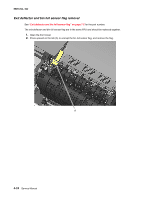
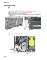
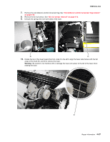
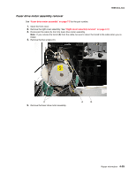
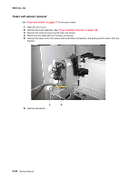
5025-2xx, 4xx Fuser drive motor assembly removal See "Fuser drive motor assembly" on page 7-5 for the part number. 1. Open the front cover. 2. Remove the right cover assembly. See "Right cover assembly removal" on page 4-10. 3. Disconnect the cable (A) from the fuser drive motor assembly. Note: If you remove the toroid (B) from the cable, be sure to return the toroid to the cable when you reinstall. 4. Remove the two screws (C). 5. Remove the fuser drive motor assembly. Repair information 4-29
-
 1
1 -
2
-
3
-
4
-
5
-
6
-
7
-
8
-
9
-
10
-
11
-
12
-
13
-
14
-
15
-
16
-
17
-
18
-
19
-
20
-
21
-
22
-
23
-
24
-
25
-
26
-
27
-
28
-
29
-
30
-
31
-
32
-
33
-
34
-
35
-
36
-
37
-
38
-
39
-
40
-
41
-
42
-
43
-
44
-
45
-
46
-
47
-
48
-
49
-
50
-
51
-
52
-
53
-
54
-
55
-
56
-
57
-
58
-
59
-
60
-
61
-
62
-
63
-
64
-
65
-
66
-
67
-
68
-
69
-
70
-
71
-
72
-
73
-
74
-
75
-
76
-
77
-
78
-
79
-
80
-
81
-
82
-
83
-
84
-
85
-
86
-
87
-
88
-
89
-
90
-
91
-
92
-
93
-
94
-
95
-
96
-
97
-
98
-
99
-
100
-
101
-
102
-
103
-
104
-
105
-
106
-
107
-
108
-
109
-
110
-
111
-
112
-
113
-
114
-
115
-
116
-
117
-
118
-
119
-
120
-
121
-
122
-
123
-
124
-
125
-
126
-
127
-
128
-
129
-
130
-
131
-
132
-
133
-
134
-
135
-
136
-
137
-
138
-
139
-
140
-
141
-
142
-
143
-
144
-
145
-
146
-
147
-
148
-
149
-
150
-
151
-
152
-
153
-
154
-
155
-
156
-
157
-
158
-
159
-
160
-
161
-
 162
162 -
 163
163 -
 164
164 -
 165
165 -
 166
166 -
 167
167 -
 168
168 -
 169
169 -
 170
170 -
 171
171 -
 172
172 -
173
-
174
-
175
-
176
-
177
-
178
-
179
-
180
-
181
-
182
-
183
-
184
-
185
-
186
-
187
-
188
-
189
-
190
-
191
-
192
-
193
-
194
-
195
-
196
-
197
-
198
-
199
-
200
-
201
-
202
-
203
-
204
-
205
-
206
-
207
-
208
-
209
-
210
-
211
-
212
-
213
-
214
-
215
-
216
-
217
-
218
-
219
-
220
-
221
-
222
-
223
-
224
-
225
-
226
-
227
-
228
-
229
-
230
-
231
-
232
-
233
-
234
-
235
-
236
 |
 |

Repair information
4-29
5025-2xx, 4xx
Fuser drive motor assembly removal
See
“Fuser drive motor assembly” on page 7-5
for the part number.
1.
Open the front cover.
2.
Remove the right cover assembly. See
“Right cover assembly removal” on page 4-10
.
3.
Disconnect the cable (A) from the fuser drive motor assembly.
Note:
If you remove the toroid (B) from the cable, be sure to return the toroid to the cable when you re-
install.
4.
Remove the two screws (C).
5.
Remove the fuser drive motor assembly.