Ricoh AC205 User's Guide - Page 256
memory DIMM slot., Push the DIMM straight into the DIMM slot until it snaps into
 |
View all Ricoh AC205 manuals
Add to My Manuals
Save this manual to your list of manuals |
Page 256 highlights
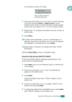
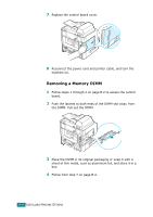
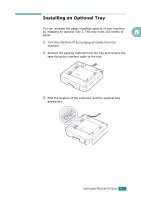
4 Remove the memory DIMM from its antistatic package. Locate the alignment notches on the bottom edge of each DIMM. Notches B Connection points 5 Holding the memory DIMM by the edges, align the notches on the memory DIMM with the grooves at the top of the memory DIMM slot. Groove Notch 6 Push the DIMM straight into the DIMM slot until it snaps into place. Make sure the latches fit over the notches located on either side of the DIMM. Notch Latch INSTALLING MACHINE OPTIONS B.3
-
 1
1 -
2
-
3
-
4
-
5
-
6
-
7
-
8
-
9
-
10
-
11
-
12
-
13
-
14
-
15
-
16
-
17
-
18
-
19
-
20
-
21
-
22
-
23
-
24
-
25
-
26
-
27
-
28
-
29
-
30
-
31
-
32
-
33
-
34
-
35
-
36
-
37
-
38
-
39
-
40
-
41
-
42
-
43
-
44
-
45
-
46
-
47
-
48
-
49
-
50
-
51
-
52
-
53
-
54
-
55
-
56
-
57
-
58
-
59
-
60
-
61
-
62
-
63
-
64
-
65
-
66
-
67
-
68
-
69
-
70
-
71
-
72
-
73
-
74
-
75
-
76
-
77
-
78
-
79
-
80
-
81
-
82
-
83
-
84
-
85
-
86
-
87
-
88
-
89
-
90
-
91
-
92
-
93
-
94
-
95
-
96
-
97
-
98
-
99
-
100
-
101
-
102
-
103
-
104
-
105
-
106
-
107
-
108
-
109
-
110
-
111
-
112
-
113
-
114
-
115
-
116
-
117
-
118
-
119
-
120
-
121
-
122
-
123
-
124
-
125
-
126
-
127
-
128
-
129
-
130
-
131
-
132
-
133
-
134
-
135
-
136
-
137
-
138
-
139
-
140
-
141
-
142
-
143
-
144
-
145
-
146
-
147
-
148
-
149
-
150
-
151
-
152
-
153
-
154
-
155
-
156
-
157
-
158
-
159
-
160
-
161
-
162
-
163
-
164
-
165
-
166
-
167
-
168
-
169
-
170
-
171
-
172
-
173
-
174
-
175
-
176
-
177
-
178
-
179
-
180
-
181
-
182
-
183
-
184
-
185
-
186
-
187
-
188
-
189
-
190
-
191
-
192
-
193
-
194
-
195
-
196
-
197
-
198
-
199
-
200
-
201
-
202
-
203
-
204
-
205
-
206
-
207
-
208
-
209
-
210
-
211
-
212
-
213
-
214
-
215
-
216
-
217
-
218
-
219
-
220
-
221
-
222
-
223
-
224
-
225
-
226
-
227
-
228
-
229
-
230
-
231
-
232
-
233
-
234
-
235
-
236
-
237
-
238
-
239
-
240
-
241
-
242
-
243
-
244
-
245
-
246
-
247
-
248
-
249
-
250
-
 251
251 -
 252
252 -
 253
253 -
 254
254 -
 255
255 -
 256
256 -
 257
257 -
 258
258 -
 259
259 -
 260
260 -
 261
261 -
262
-
263
-
264
-
265
-
266
-
267
-
268
-
269
-
270
-
271
-
272
-
273
-
274
-
275
-
276
-
277
-
278
 |
 |
B
I
NSTALLING
M
ACHINE
O
PTIONS
B.3
4
Remove the memory DIMM from its antistatic package.
Locate the alignment notches on the bottom edge of each
DIMM.
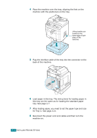
5
Holding the memory DIMM by the edges, align the notches
on the memory DIMM with the grooves at the top of the
memory DIMM slot.
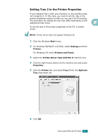
6
Push the DIMM straight into the DIMM slot until it snaps into
place. Make sure the latches fit over the notches located on
either side of the DIMM.
Connection
points
Notches
Groove
Notch
Latch
Notch