Dell PowerEdge R815 Hardware Owner's Manual - Page 117
Installing the Integrated Storage Controller Card, See
 |
View all Dell PowerEdge R815 manuals
Add to My Manuals
Save this manual to your list of manuals |
Page 117 highlights
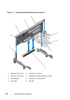
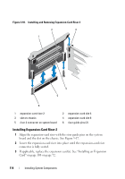
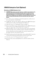
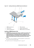
Installing the Integrated Storage Controller Card CAUTION: Many repairs may only be done by a certified service technician. You should only perform troubleshooting and simple repairs as authorized in your product documentation, or as directed by the online or telephone service and support team. Damage due to servicing that is not authorized by Dell is not covered by your warranty. Read and follow the safety instructions that came with the product. 1 Turn off the system, including any attached peripherals, and disconnect the system from the electrical outlet. 2 Open the system. See "Opening the System" on page 76. 3 Remove the cooling shroud. See "Removing the Cooling Shroud" on page 88. 4 Remove the cooling fan assembly. See "Removing the Cooling Fan Assembly" on page 102. 5 Hold the card by its edges and angle it between the alignment guides on riser 1 until it is fully seated. See Figure 3-1. 6 Connect the SAS data cables to the integrated storage controller card. See Figure 3-19. NOTE: Ensure that you connect the cable according to the connector labels on the cable. The cable does not function properly if reversed. 7 If applicable, connect the RAID battery cable. See Figure 3-20. 8 Route the SAS data cable through the channel on the inner side of the chassis. 9 Attach the cable labeled "SAS A" to SAS A connector on the backplane, and attach the cable labeled "SAS B" to SAS B connector on the backplane. See Figure 3-19. 10 Replace the cooling fan assembly. See "Installing the Cooling Fan Assembly" on page 104. 11 Replace the cooling shroud. See "Installing the Cooling Shroud" on page 89. 12 Close the system. See "Closing the System" on page 77. 13 Reconnect the system to its electrical outlet and turn the system on, including any attached peripherals. Installing System Components 117
-
 1
1 -
2
-
3
-
4
-
5
-
6
-
7
-
8
-
9
-
10
-
11
-
12
-
13
-
14
-
15
-
16
-
17
-
18
-
19
-
20
-
21
-
22
-
23
-
24
-
25
-
26
-
27
-
28
-
29
-
30
-
31
-
32
-
33
-
34
-
35
-
36
-
37
-
38
-
39
-
40
-
41
-
42
-
43
-
44
-
45
-
46
-
47
-
48
-
49
-
50
-
51
-
52
-
53
-
54
-
55
-
56
-
57
-
58
-
59
-
60
-
61
-
62
-
63
-
64
-
65
-
66
-
67
-
68
-
69
-
70
-
71
-
72
-
73
-
74
-
75
-
76
-
77
-
78
-
79
-
80
-
81
-
82
-
83
-
84
-
85
-
86
-
87
-
88
-
89
-
90
-
91
-
92
-
93
-
94
-
95
-
96
-
97
-
98
-
99
-
100
-
101
-
102
-
103
-
104
-
105
-
106
-
107
-
108
-
109
-
110
-
111
-
 112
112 -
 113
113 -
 114
114 -
 115
115 -
 116
116 -
 117
117 -
 118
118 -
 119
119 -
 120
120 -
 121
121 -
 122
122 -
123
-
124
-
125
-
126
-
127
-
128
-
129
-
130
-
131
-
132
-
133
-
134
-
135
-
136
-
137
-
138
-
139
-
140
-
141
-
142
-
143
-
144
-
145
-
146
-
147
-
148
-
149
-
150
-
151
-
152
-
153
-
154
-
155
-
156
-
157
-
158
-
159
-
160
-
161
-
162
-
163
-
164
-
165
-
166
-
167
-
168
-
169
-
170
-
171
-
172
-
173
-
174
-
175
-
176
-
177
-
178
-
179
-
180
-
181
-
182
-
183
-
184
-
185
-
186
-
187
-
188
-
189
-
190
 |
 |
