Dell PowerEdge R815 Hardware Owner's Manual - Page 19
Indicator, Button, or, Connector, Description, PCI Express Generation 2 x4 link
 |
View all Dell PowerEdge R815 manuals
Add to My Manuals
Save this manual to your list of manuals |
Page 19 highlights
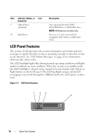
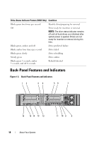
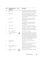
Item Indicator, Button, or Icon Connector 1 PCIe slot 1 2 PCIe slot 2 3 PCIe slot 3 4 PCIe slot 4 5 PCIe slot 5 6 PCIe slot 6 7 Power supplies (2) 8 System identification button 9 System status indicator 10 System identification connector 11 Ethernet connectors (4) Description PCI Express (Generation 2) x8 link expansion slot (24.13 cm [9.5"] length). PCI Express (Generation 2) x4 link expansion slot (low-profile 24.13 cm [9.5"] maximum length, with a standard height bracket). PCI Express (Generation 2) x8 link expansion slot (low-profile 24.13 cm [9.5"] length). PCI Express (Generation 2) x8 link expansion slot (low-profile 24.13 cm [9.5"] length). PCI Express (Generation 2) x8 link expansion slot (24.13 cm [9.5"] length). PCI Express (Generation 2) x8 link expansion slot (24.13 cm [9.5"] length). 1100 W power supplies. The identification buttons on the front and back panels can be used to locate a particular system within a rack. When one of these buttons is pushed, the LCD panel on the front and the system status indicator on the back blink until one of the buttons is pushed again. Lights blue during normal system operation. Lights amber when the system needs attention due to a problem. Connects the optional system status indicator assembly through the optional cable management arm. Integrated 10/100/1000 NIC connectors. About Your System 19
-
 1
1 -
2
-
3
-
4
-
5
-
6
-
7
-
8
-
9
-
10
-
11
-
12
-
13
-
 14
14 -
 15
15 -
 16
16 -
 17
17 -
 18
18 -
 19
19 -
 20
20 -
 21
21 -
 22
22 -
 23
23 -
 24
24 -
25
-
26
-
27
-
28
-
29
-
30
-
31
-
32
-
33
-
34
-
35
-
36
-
37
-
38
-
39
-
40
-
41
-
42
-
43
-
44
-
45
-
46
-
47
-
48
-
49
-
50
-
51
-
52
-
53
-
54
-
55
-
56
-
57
-
58
-
59
-
60
-
61
-
62
-
63
-
64
-
65
-
66
-
67
-
68
-
69
-
70
-
71
-
72
-
73
-
74
-
75
-
76
-
77
-
78
-
79
-
80
-
81
-
82
-
83
-
84
-
85
-
86
-
87
-
88
-
89
-
90
-
91
-
92
-
93
-
94
-
95
-
96
-
97
-
98
-
99
-
100
-
101
-
102
-
103
-
104
-
105
-
106
-
107
-
108
-
109
-
110
-
111
-
112
-
113
-
114
-
115
-
116
-
117
-
118
-
119
-
120
-
121
-
122
-
123
-
124
-
125
-
126
-
127
-
128
-
129
-
130
-
131
-
132
-
133
-
134
-
135
-
136
-
137
-
138
-
139
-
140
-
141
-
142
-
143
-
144
-
145
-
146
-
147
-
148
-
149
-
150
-
151
-
152
-
153
-
154
-
155
-
156
-
157
-
158
-
159
-
160
-
161
-
162
-
163
-
164
-
165
-
166
-
167
-
168
-
169
-
170
-
171
-
172
-
173
-
174
-
175
-
176
-
177
-
178
-
179
-
180
-
181
-
182
-
183
-
184
-
185
-
186
-
187
-
188
-
189
-
190
 |
 |
