Dell PowerEdge R815 Hardware Owner's Manual - Page 83
Optical Drive, Removing an Optical Drive
 |
View all Dell PowerEdge R815 manuals
Add to My Manuals
Save this manual to your list of manuals |
Page 83 highlights
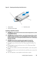
Optical Drive Your system is provided with an optional slimline SATA DVD-ROM or DVD+/RW optical drive. NOTE: DVD devices are data only. Removing an Optical Drive CAUTION: Many repairs may only be done by a certified service technician. You should only perform troubleshooting and simple repairs as authorized in your product documentation, or as directed by the online or telephone service and support team. Damage due to servicing that is not authorized by Dell is not covered by your warranty. Read and follow the safety instructions that came with the product. 1 If installed, remove the front bezel. See "Removing the Front Bezel" on page 75. 2 Turn off the system, including any attached peripherals, and disconnect the system from its electrical outlet. 3 Open the system. See "Opening the System" on page 76. 4 Disconnect the power/data cable from the back of the drive. Note the routing of the power/data cable inside the system as you remove them from the system board and the drive. Route these cables properly when you replace them to prevent them from being pinched or crimped. For more information, see "Front-Chassis Assembly" on page 90. 5 To remove the drive, press down and push the blue release tab toward the front of the system. See Figure 3-7. 6 Slide the optical drive out of the system until it is free of the drive bay. 7 If you are not installing a new optical drive, install the optical drive insert. 8 Close the system. See "Closing the System" on page 77. 9 Reconnect the system to its electrical outlet and turn the system on, including any attached peripherals. 10 If applicable, replace the front bezel. See "Installing the Front Bezel" on page 75. Installing System Components 83
-
 1
1 -
2
-
3
-
4
-
5
-
6
-
7
-
8
-
9
-
10
-
11
-
12
-
13
-
14
-
15
-
16
-
17
-
18
-
19
-
20
-
21
-
22
-
23
-
24
-
25
-
26
-
27
-
28
-
29
-
30
-
31
-
32
-
33
-
34
-
35
-
36
-
37
-
38
-
39
-
40
-
41
-
42
-
43
-
44
-
45
-
46
-
47
-
48
-
49
-
50
-
51
-
52
-
53
-
54
-
55
-
56
-
57
-
58
-
59
-
60
-
61
-
62
-
63
-
64
-
65
-
66
-
67
-
68
-
69
-
70
-
71
-
72
-
73
-
74
-
75
-
76
-
77
-
 78
78 -
 79
79 -
 80
80 -
 81
81 -
 82
82 -
 83
83 -
 84
84 -
 85
85 -
 86
86 -
 87
87 -
 88
88 -
89
-
90
-
91
-
92
-
93
-
94
-
95
-
96
-
97
-
98
-
99
-
100
-
101
-
102
-
103
-
104
-
105
-
106
-
107
-
108
-
109
-
110
-
111
-
112
-
113
-
114
-
115
-
116
-
117
-
118
-
119
-
120
-
121
-
122
-
123
-
124
-
125
-
126
-
127
-
128
-
129
-
130
-
131
-
132
-
133
-
134
-
135
-
136
-
137
-
138
-
139
-
140
-
141
-
142
-
143
-
144
-
145
-
146
-
147
-
148
-
149
-
150
-
151
-
152
-
153
-
154
-
155
-
156
-
157
-
158
-
159
-
160
-
161
-
162
-
163
-
164
-
165
-
166
-
167
-
168
-
169
-
170
-
171
-
172
-
173
-
174
-
175
-
176
-
177
-
178
-
179
-
180
-
181
-
182
-
183
-
184
-
185
-
186
-
187
-
188
-
189
-
190
 |
 |
