Dell PowerEdge R815 Hardware Owner's Manual - Page 130
place the heat sink on the processor. See
 |
View all Dell PowerEdge R815 manuals
Add to My Manuals
Save this manual to your list of manuals |
Page 130 highlights
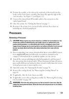
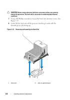
10 Rotate the socket-release lever down until it snaps into place. See Figure 3-24. NOTE: Your kit may contain a replacement heat sink if you are installing a processor that consumes additional power. The new heat sink may not appear different than the original one; however, it has improved thermal dissipation specifications and must be used. 11 Using a clean lint-free cloth, remove the thermal grease from the heat sink. CAUTION: Applying too much thermal grease can result in excess grease coming in contact with and contaminating the processor socket. 12 Keeping the heat sink pin aligned with the slot on the system board, place the heat sink on the processor. See Figure 3-23. 13 Using a #2 Phillips screwdriver, tighten the two heat-sink retention screws. See Figure 3-23. 14 If applicable, replace the cooling fan assembly. See "Installing the Cooling Fan Assembly" on page 104. 15 Replace the cooling shroud. See "Installing the Cooling Shroud" on page 89. 16 If applicable, slide the front chassis assembly back. See "Front-Chassis Assembly" on page 90. 17 Close the system. See "Closing the System" on page 77. 18 Reconnect your system and peripherals to their electrical outlets, and turn on the system. 19 Press to enter the System Setup program, and check that the processor information matches the new system configuration. See "Entering the System Setup Program" on page 54. 20 Run the system diagnostics to verify that the new processor operates correctly. For information about running the diagnostics, see "Running the Embedded System Diagnostics" on page 172. 130 Installing System Components
-
 1
1 -
2
-
3
-
4
-
5
-
6
-
7
-
8
-
9
-
10
-
11
-
12
-
13
-
14
-
15
-
16
-
17
-
18
-
19
-
20
-
21
-
22
-
23
-
24
-
25
-
26
-
27
-
28
-
29
-
30
-
31
-
32
-
33
-
34
-
35
-
36
-
37
-
38
-
39
-
40
-
41
-
42
-
43
-
44
-
45
-
46
-
47
-
48
-
49
-
50
-
51
-
52
-
53
-
54
-
55
-
56
-
57
-
58
-
59
-
60
-
61
-
62
-
63
-
64
-
65
-
66
-
67
-
68
-
69
-
70
-
71
-
72
-
73
-
74
-
75
-
76
-
77
-
78
-
79
-
80
-
81
-
82
-
83
-
84
-
85
-
86
-
87
-
88
-
89
-
90
-
91
-
92
-
93
-
94
-
95
-
96
-
97
-
98
-
99
-
100
-
101
-
102
-
103
-
104
-
105
-
106
-
107
-
108
-
109
-
110
-
111
-
112
-
113
-
114
-
115
-
116
-
117
-
118
-
119
-
120
-
121
-
122
-
123
-
124
-
 125
125 -
 126
126 -
 127
127 -
 128
128 -
 129
129 -
 130
130 -
 131
131 -
 132
132 -
 133
133 -
 134
134 -
 135
135 -
136
-
137
-
138
-
139
-
140
-
141
-
142
-
143
-
144
-
145
-
146
-
147
-
148
-
149
-
150
-
151
-
152
-
153
-
154
-
155
-
156
-
157
-
158
-
159
-
160
-
161
-
162
-
163
-
164
-
165
-
166
-
167
-
168
-
169
-
170
-
171
-
172
-
173
-
174
-
175
-
176
-
177
-
178
-
179
-
180
-
181
-
182
-
183
-
184
-
185
-
186
-
187
-
188
-
189
-
190
 |
 |
