Dell PowerEdge R815 Hardware Owner's Manual - Page 85
Power Supplies
 |
View all Dell PowerEdge R815 manuals
Add to My Manuals
Save this manual to your list of manuals |
Page 85 highlights
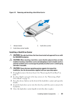
5 Connect the power/data cable to the back of the drive and to the system board. Route the cable properly inside the system to prevent it from being pinched or crimped. For more information, see "Front-Chassis Assembly" on page 90. 6 Close the system. See "Closing the System" on page 77. 7 Reconnect the system to its electrical outlet and turn the system on, including any attached peripherals. 8 If applicable, replace the front bezel. See "Installing the Front Bezel" on page 75. Power Supplies Your system supports two hot-swappable 1100 W power supplies. If two power supplies are installed, the second power supply provides, power redundancy. In a redundant mode, the system distributes the power load across both power supplies to maximize efficiency. When a power supply is removed with the system powered on, the full power load is picked up by the second power supply. Table 3-1 lists the power supply redundancy modes. Table 3-1. Power Supply Redundancy Modes Number of Power Supplies Redundancy Mode 1 1+0 2 1+1 System Configuration Nonredundant configuration Redundant configuration Installing System Components 85
-
 1
1 -
2
-
3
-
4
-
5
-
6
-
7
-
8
-
9
-
10
-
11
-
12
-
13
-
14
-
15
-
16
-
17
-
18
-
19
-
20
-
21
-
22
-
23
-
24
-
25
-
26
-
27
-
28
-
29
-
30
-
31
-
32
-
33
-
34
-
35
-
36
-
37
-
38
-
39
-
40
-
41
-
42
-
43
-
44
-
45
-
46
-
47
-
48
-
49
-
50
-
51
-
52
-
53
-
54
-
55
-
56
-
57
-
58
-
59
-
60
-
61
-
62
-
63
-
64
-
65
-
66
-
67
-
68
-
69
-
70
-
71
-
72
-
73
-
74
-
75
-
76
-
77
-
78
-
79
-
 80
80 -
 81
81 -
 82
82 -
 83
83 -
 84
84 -
 85
85 -
 86
86 -
 87
87 -
 88
88 -
 89
89 -
 90
90 -
91
-
92
-
93
-
94
-
95
-
96
-
97
-
98
-
99
-
100
-
101
-
102
-
103
-
104
-
105
-
106
-
107
-
108
-
109
-
110
-
111
-
112
-
113
-
114
-
115
-
116
-
117
-
118
-
119
-
120
-
121
-
122
-
123
-
124
-
125
-
126
-
127
-
128
-
129
-
130
-
131
-
132
-
133
-
134
-
135
-
136
-
137
-
138
-
139
-
140
-
141
-
142
-
143
-
144
-
145
-
146
-
147
-
148
-
149
-
150
-
151
-
152
-
153
-
154
-
155
-
156
-
157
-
158
-
159
-
160
-
161
-
162
-
163
-
164
-
165
-
166
-
167
-
168
-
169
-
170
-
171
-
172
-
173
-
174
-
175
-
176
-
177
-
178
-
179
-
180
-
181
-
182
-
183
-
184
-
185
-
186
-
187
-
188
-
189
-
190
 |
 |
