Dell PowerEdge R815 Hardware Owner's Manual - Page 125
Processors, Removing a Processor
 |
View all Dell PowerEdge R815 manuals
Add to My Manuals
Save this manual to your list of manuals |
Page 125 highlights
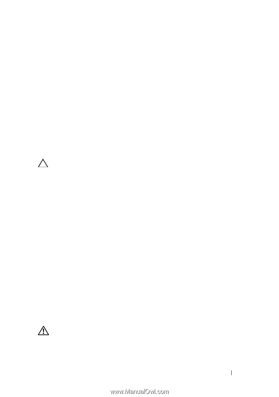
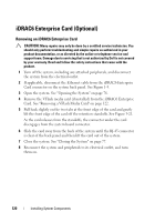
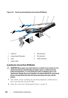
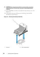
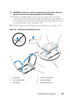
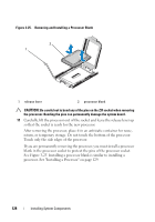
3 Position the module so the tabs on the underside of the tray fit into the hooks on the front-chassis assembly, then lower the opposite edge of the card into place. See Figure 3-1 and Figure 3-22. 4 Connect the internal dual SD module cable to the connector on the control panel board. 5 Close the system. See "Closing the System" on page 77. 6 Reconnect the system to its electrical outlet and turn the system on, including any attached peripherals. Processors Removing a Processor CAUTION: Many repairs may only be done by a certified service technician. You should only perform troubleshooting and simple repairs as authorized in your product documentation, or as directed by the online or telephone service and support team. Damage due to servicing that is not authorized by Dell is not covered by your warranty. Read and follow the safety instructions that came with the product. 1 Prior to upgrading your system, download the latest system BIOS version from support.dell.com and follow the instructions included in the compressed download file to install the update on your system. 2 Turn off the system, including any attached peripherals, and disconnect the system from the electrical outlet. When disconnected from AC power, press and hold the power button for three seconds to fully drain the system of stored power prior to removing the cover. 3 Open the system. See "Opening the System" on page 76. 4 Remove the cooling shroud. See "Removing the Cooling Shroud" on page 88. 5 If applicable, slide the front chassis assembly. 6 If applicable, remove the cooling fan assembly. See "Removing the Cooling Fan Assembly" on page 102. WARNING: The heat sink and processor are hot to touch for some time after the system has been powered down. Allow the heat sink and processor to cool before handling them. Installing System Components 125
-
 1
1 -
2
-
3
-
4
-
5
-
6
-
7
-
8
-
9
-
10
-
11
-
12
-
13
-
14
-
15
-
16
-
17
-
18
-
19
-
20
-
21
-
22
-
23
-
24
-
25
-
26
-
27
-
28
-
29
-
30
-
31
-
32
-
33
-
34
-
35
-
36
-
37
-
38
-
39
-
40
-
41
-
42
-
43
-
44
-
45
-
46
-
47
-
48
-
49
-
50
-
51
-
52
-
53
-
54
-
55
-
56
-
57
-
58
-
59
-
60
-
61
-
62
-
63
-
64
-
65
-
66
-
67
-
68
-
69
-
70
-
71
-
72
-
73
-
74
-
75
-
76
-
77
-
78
-
79
-
80
-
81
-
82
-
83
-
84
-
85
-
86
-
87
-
88
-
89
-
90
-
91
-
92
-
93
-
94
-
95
-
96
-
97
-
98
-
99
-
100
-
101
-
102
-
103
-
104
-
105
-
106
-
107
-
108
-
109
-
110
-
111
-
112
-
113
-
114
-
115
-
116
-
117
-
118
-
119
-
 120
120 -
 121
121 -
 122
122 -
 123
123 -
 124
124 -
 125
125 -
 126
126 -
 127
127 -
 128
128 -
 129
129 -
 130
130 -
131
-
132
-
133
-
134
-
135
-
136
-
137
-
138
-
139
-
140
-
141
-
142
-
143
-
144
-
145
-
146
-
147
-
148
-
149
-
150
-
151
-
152
-
153
-
154
-
155
-
156
-
157
-
158
-
159
-
160
-
161
-
162
-
163
-
164
-
165
-
166
-
167
-
168
-
169
-
170
-
171
-
172
-
173
-
174
-
175
-
176
-
177
-
178
-
179
-
180
-
181
-
182
-
183
-
184
-
185
-
186
-
187
-
188
-
189
-
190
 |
 |