IBM 620410U User Guide - Page 79
system resources. Then, the system starts the PCI devices in the following order
 |
UPC - 087944665410
View all IBM 620410U manuals
Add to My Manuals
Save this manual to your list of manuals |
Page 79 highlights
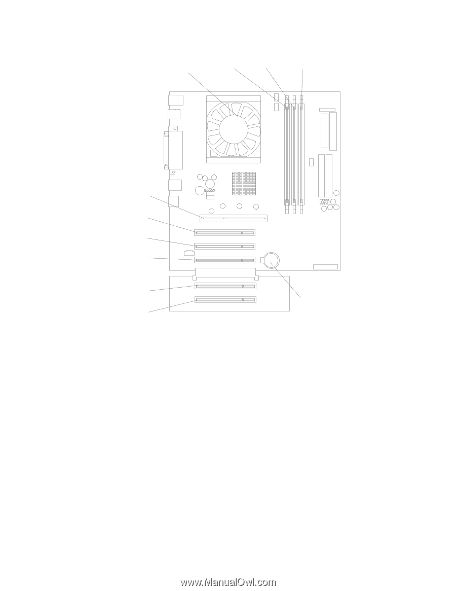
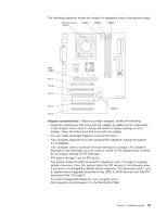
The following illustration shows the location of expansion slots on the system board. Microprocessor (J4K1) DIMM 1 DIMM 2 DIMM 3 AGP (J5E1) PCI 1 PCI 2 PCI 3 PCI 4 PCI 5 Battery Adapter considerations: Before you install adapters, review the following: v Follow the instructions that come with the adapter in addition to the instructions in this chapter. If you need to change the switch or jumper settings on your adapter, follow the instructions that come with the adapter. v You can install full-length adapters in all five PCI slots. v Your computer supports 5.0 V and universal PCI adapters; it does not support 3.3 V adapters. v Your computer uses a rotational interrupt technique to configure PCI adapters. Because of this technique, you can install a variety of PCI adapters that currently do not support sharing of PCI interrupts. v PCI slots 1 through 5 are on PCI bus 0. The system scans the AGP slot and PCI expansion slots 1 through 5 to assign system resources. Then, the system starts the PCI devices in the following order, if you have not changed the default startup sequence: PCI expansion slots 1 and 2, system board integrated drive electronics (IDE) or SCSI devices, and then PCI expansion slots 3 through 5. v For a list of supported options for your computer, go to http://www.ibm.com/pc/support/ on the World Wide Web. Chapter 5. Installing options 63
-
 1
1 -
2
-
3
-
4
-
5
-
6
-
7
-
8
-
9
-
10
-
11
-
12
-
13
-
14
-
15
-
16
-
17
-
18
-
19
-
20
-
21
-
22
-
23
-
24
-
25
-
26
-
27
-
28
-
29
-
30
-
31
-
32
-
33
-
34
-
35
-
36
-
37
-
38
-
39
-
40
-
41
-
42
-
43
-
44
-
45
-
46
-
47
-
48
-
49
-
50
-
51
-
52
-
53
-
54
-
55
-
56
-
57
-
58
-
59
-
60
-
61
-
62
-
63
-
64
-
65
-
66
-
67
-
68
-
69
-
70
-
71
-
72
-
73
-
 74
74 -
 75
75 -
 76
76 -
 77
77 -
 78
78 -
 79
79 -
 80
80 -
 81
81 -
 82
82 -
 83
83 -
 84
84 -
85
-
86
-
87
-
88
-
89
-
90
-
91
-
92
-
93
-
94
-
95
-
96
-
97
-
98
-
99
-
100
-
101
-
102
-
103
-
104
-
105
-
106
-
107
-
108
-
109
-
110
-
111
-
112
-
113
-
114
-
115
-
116
-
117
-
118
-
119
-
120
-
121
-
122
-
123
-
124
-
125
-
126
-
127
-
128
-
129
-
130
-
131
-
132
-
133
-
134
-
135
-
136
-
137
-
138
-
139
-
140
-
141
-
142
-
143
-
144
-
145
-
146
-
147
-
148
-
149
-
150
-
151
-
152
-
153
-
154
-
155
-
156
-
157
-
158
-
159
-
160
-
161
-
162
-
163
-
164
-
165
-
166
 |
 |