IBM 620410U User Guide - Page 87
Installing a hard disk drive in bay 5
 |
UPC - 087944665410
View all IBM 620410U manuals
Add to My Manuals
Save this manual to your list of manuals |
Page 87 highlights
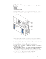
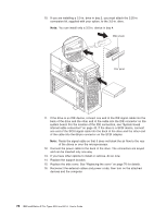
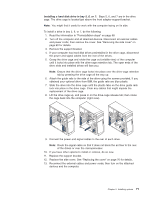
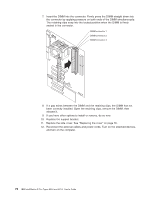
Installing a hard disk drive in bay 5, 6, or 7: Bays 5, 6, and 7 are in the drive cage. The drive cage is located just above the front adapter-support bracket. Note: You might find it useful to work with the computer laying on its side. To install a drive in bay 5, 6, or 7, do the following: 1. Read the information in "Preinstallation steps" on page 68. 2. Turn off the computer and all attached devices. Disconnect all external cables and power cords; then remove the cover. See "Removing the side cover" on page 60 for details. 3. Remove the support bracket. 4. If your computer has hard disk drives preinstalled in the drive cage, disconnect the power and signal cables from the rear of the drives. 5. Grasp the drive cage and rotate the cage out (middle view) of the computer until it locks into place with the drive-cage retention tab. The open ends of the drive slots and installed drives will face you. Note: Ensure that the drive cage locks into place over the drive-cage retention tab by pressing the drive cage all the way up. 6. Attach the guide rails to the side of the drive using the screws provided. If you obtained your optional drive from IBM, the guide rails are blue plastic. 7. Slide the drive into the drive cage until the plastic tabs on the drive guide rails lock into place in the drive cage. Clear any cables that might impede the replacement of the drive cage. 8. Lift the drive cage up, and press in on the drive-cage release tab; then rotate the cage back into the computer (right view). 9. Connect the power and signal cables to the rear of each drive. Note: Route the signal cable so that it does not block the air flow to the rear of the drives or over the microprocessor. 10. If you have other options to install or remove, do so now. 11. Replace the support bracket. 12. Replace the side cover. See "Replacing the cover" on page 76 for details. 13. Reconnect the external cables and power cords; then turn on the attached devices and the computer. Chapter 5. Installing options 71
-
 1
1 -
2
-
3
-
4
-
5
-
6
-
7
-
8
-
9
-
10
-
11
-
12
-
13
-
14
-
15
-
16
-
17
-
18
-
19
-
20
-
21
-
22
-
23
-
24
-
25
-
26
-
27
-
28
-
29
-
30
-
31
-
32
-
33
-
34
-
35
-
36
-
37
-
38
-
39
-
40
-
41
-
42
-
43
-
44
-
45
-
46
-
47
-
48
-
49
-
50
-
51
-
52
-
53
-
54
-
55
-
56
-
57
-
58
-
59
-
60
-
61
-
62
-
63
-
64
-
65
-
66
-
67
-
68
-
69
-
70
-
71
-
72
-
73
-
74
-
75
-
76
-
77
-
78
-
79
-
80
-
81
-
 82
82 -
 83
83 -
 84
84 -
 85
85 -
 86
86 -
 87
87 -
 88
88 -
 89
89 -
 90
90 -
 91
91 -
 92
92 -
93
-
94
-
95
-
96
-
97
-
98
-
99
-
100
-
101
-
102
-
103
-
104
-
105
-
106
-
107
-
108
-
109
-
110
-
111
-
112
-
113
-
114
-
115
-
116
-
117
-
118
-
119
-
120
-
121
-
122
-
123
-
124
-
125
-
126
-
127
-
128
-
129
-
130
-
131
-
132
-
133
-
134
-
135
-
136
-
137
-
138
-
139
-
140
-
141
-
142
-
143
-
144
-
145
-
146
-
147
-
148
-
149
-
150
-
151
-
152
-
153
-
154
-
155
-
156
-
157
-
158
-
159
-
160
-
161
-
162
-
163
-
164
-
165
-
166
 |
 |
