IBM 620410U User Guide - Page 86
If you have other options to install or remove, do so now., and can be inserted only one way.
 |
UPC - 087944665410
View all IBM 620410U manuals
Add to My Manuals
Save this manual to your list of manuals |
Page 86 highlights
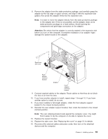
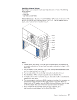
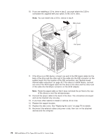
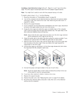
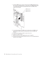
10. If you are installing a 3.5-in. drive in bay 2, you must attach the 5.25-in conversion kit, supplied with your option, to the 3.5-in. drive. Note: You can install only a 3.5-in. device in bay 4. 11. If the drive is an IDE device, connect one end of the IDE signal cable into the back of the drive and the other end of the cable into the IDE connector on the system board. For the location of the IDE connectors, see "System board internal cable connectors" on page 42. If the drive is a SCSI device, connect one end of the SCSI signal cable into the back of the drive and the other end of the cable into the 68-pin connector on the SCSI adapter. Note: Route the signal cable so that it does not block the air flow to the rear of the drives or over the microprocessor. 12. Connect the power cable to the back of the drive. The connectors are keyed and can be inserted only one way. 13. If you have other options to install or remove, do so now. 14. Replace the support bracket. 15. Replace the side cover. See "Replacing the cover" on page 76 for details. 16. Reconnect the external cables and power cords; then turn on the attached devices and the computer. 70 IBM IntelliStation E Pro Types 6204 and 6214: User's Guide
-
 1
1 -
2
-
3
-
4
-
5
-
6
-
7
-
8
-
9
-
10
-
11
-
12
-
13
-
14
-
15
-
16
-
17
-
18
-
19
-
20
-
21
-
22
-
23
-
24
-
25
-
26
-
27
-
28
-
29
-
30
-
31
-
32
-
33
-
34
-
35
-
36
-
37
-
38
-
39
-
40
-
41
-
42
-
43
-
44
-
45
-
46
-
47
-
48
-
49
-
50
-
51
-
52
-
53
-
54
-
55
-
56
-
57
-
58
-
59
-
60
-
61
-
62
-
63
-
64
-
65
-
66
-
67
-
68
-
69
-
70
-
71
-
72
-
73
-
74
-
75
-
76
-
77
-
78
-
79
-
80
-
 81
81 -
 82
82 -
 83
83 -
 84
84 -
 85
85 -
 86
86 -
 87
87 -
 88
88 -
 89
89 -
 90
90 -
 91
91 -
92
-
93
-
94
-
95
-
96
-
97
-
98
-
99
-
100
-
101
-
102
-
103
-
104
-
105
-
106
-
107
-
108
-
109
-
110
-
111
-
112
-
113
-
114
-
115
-
116
-
117
-
118
-
119
-
120
-
121
-
122
-
123
-
124
-
125
-
126
-
127
-
128
-
129
-
130
-
131
-
132
-
133
-
134
-
135
-
136
-
137
-
138
-
139
-
140
-
141
-
142
-
143
-
144
-
145
-
146
-
147
-
148
-
149
-
150
-
151
-
152
-
153
-
154
-
155
-
156
-
157
-
158
-
159
-
160
-
161
-
162
-
163
-
164
-
165
-
166
 |
 |
