Lenovo NetVista X40 Quick Reference for NetVista 2179 and 6643 systems (Dutch) - Page 116
Flash Utility starts., cables and power cords.
 |
View all Lenovo NetVista X40 manuals
Add to My Manuals
Save this manual to your list of manuals |
Page 116 highlights
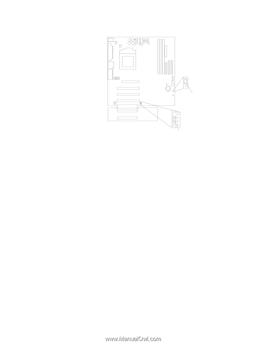
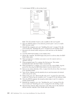
4. Locate jumper JROM1 on the system board. 1 2 3 CMOS jumper (JBAT1) 3 2 1 Boot block jumper (JROM1) Note: The PCI extender board is only available in the tower model. 5. Move the JROM1 jumper to the alternate position (pins 1 and 2) to enable BIOS recovery mode. 6. Reinstall the computer cover, see "Installing the cover" on page 58 for the tower model and "Installing the cover" on page 69 for the desktop model. 7. Reconnect all external cables and power cords and turn on the attached devices. 8. Insert the BIOS flash diskette in the diskette drive. 9. Restart the computer. The BIOS begins the power-on self-test; then, the BIOS Flash Utility starts. 10. When prompted as to whether you want to save the current code to a diskette, select N. 11. When prompted enter Y to continue the flash process. The system automatically starts the Flash Utility a second time. 12. When prompted as to whether you want to save the current BIOS, stop the process by removing the BIOS flash diskette from the diskette drive. 13. Remove any media (diskettes, CDs, or tapes) from the drives; then, shut down your operating system. 14. Turn off the computer and all attached devices and disconnect all external cables and power cords. 15. Remove the cover. See "Removing the side cover" on page 45 for the tower model and "Removing the computer cover" on page 59 for the desktop model. 16. Move the JROM1 jumperto the normal position (pins 2 and 3) to return to normal startup mode. 17. Reinstall the computer cover. See "Installing the cover" on page 58 for the tower model and "Installing the cover" on page 58 for the desktop model. 18. Reconnect the external cables and power cords; then, turn on the attached devices and the computer. They should start up normally. 100 IBM® IntelliStation® E Pro: User's Guide IntelliStation E Pro Types 6836, 6846
-
 1
1 -
2
-
3
-
4
-
5
-
6
-
7
-
8
-
9
-
10
-
11
-
12
-
13
-
14
-
15
-
16
-
17
-
18
-
19
-
20
-
21
-
22
-
23
-
24
-
25
-
26
-
27
-
28
-
29
-
30
-
31
-
32
-
33
-
34
-
35
-
36
-
37
-
38
-
39
-
40
-
41
-
42
-
43
-
44
-
45
-
46
-
47
-
48
-
49
-
50
-
51
-
52
-
53
-
54
-
55
-
56
-
57
-
58
-
59
-
60
-
61
-
62
-
63
-
64
-
65
-
66
-
67
-
68
-
69
-
70
-
71
-
72
-
73
-
74
-
75
-
76
-
77
-
78
-
79
-
80
-
81
-
82
-
83
-
84
-
85
-
86
-
87
-
88
-
89
-
90
-
91
-
92
-
93
-
94
-
95
-
96
-
97
-
98
-
99
-
100
-
101
-
102
-
103
-
104
-
105
-
106
-
107
-
108
-
109
-
110
-
 111
111 -
 112
112 -
 113
113 -
 114
114 -
 115
115 -
 116
116 -
 117
117 -
 118
118 -
 119
119 -
 120
120 -
 121
121 -
122
-
123
-
124
-
125
-
126
-
127
-
128
-
129
-
130
-
131
-
132
-
133
-
134
-
135
-
136
-
137
-
138
-
139
-
140
-
141
-
142
-
143
-
144
-
145
-
146
-
147
-
148
-
149
-
150
-
151
-
152
-
153
-
154
-
155
-
156
 |
 |