Lenovo NetVista X40 Quick Reference for NetVista 2179 and 6643 systems (Dutch) - Page 88
Input/Output connectors, Mouse connector, Keyboard connector, Parallel connector
 |
View all Lenovo NetVista X40 manuals
Add to My Manuals
Save this manual to your list of manuals |
Page 88 highlights
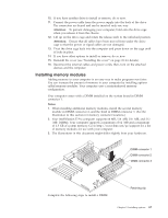
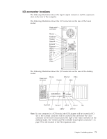
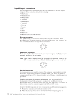
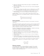
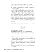
Input/Output connectors This section provides information about the I/O connectors on the rear of your computer. These connectors include the following: v One mouse v One keyboard v One parallel v Two serial v One Ethernet v Two USB v Line out v Line in v Mic v MIDI v One video v One Ultra160 SCSI (some models) Mouse connector The system board has one mouse connector that supports a mouse or other pointing device. The mouse connector is located on the rear of your computer. See "I/O connector locations" on page 71 for its location. 6 4 2 5 3 1 Keyboard connector There is one keyboard connector on the rear of your computer. See "I/O connector locations" on page 71 for its location. Note: If you attach a standard (non-USB) keyboard to the keyboard connector, the USB connectors and devices will be disabled during the power-on self-test. 6 4 2 5 3 1 Parallel connector Your computer has one parallel connector. This connector supports three standard Institute of Electrical and Electronics Engineers (IEEE) 1284 modes of operation: standard parallel port (SPP), enhanced parallel port (EPP), and extended capability port (ECP). Viewing or changing the connector assignments: You can use the built-in Configuration/Setup Utility program to configure the parallel connector as bidirectional; that is, so that data can be both read from and written to a device. In bidirectional mode, the computer supports the ECP and EPP modes. Complete the following steps to view or change the parallel-connector assignment. 1. Restart the computer and watch the monitor screen. 2. When the message Press F1 for Configuration/Setup appears, press F1. 72 IBM® IntelliStation® E Pro: User's Guide IntelliStation E Pro Types 6836, 6846
-
 1
1 -
2
-
3
-
4
-
5
-
6
-
7
-
8
-
9
-
10
-
11
-
12
-
13
-
14
-
15
-
16
-
17
-
18
-
19
-
20
-
21
-
22
-
23
-
24
-
25
-
26
-
27
-
28
-
29
-
30
-
31
-
32
-
33
-
34
-
35
-
36
-
37
-
38
-
39
-
40
-
41
-
42
-
43
-
44
-
45
-
46
-
47
-
48
-
49
-
50
-
51
-
52
-
53
-
54
-
55
-
56
-
57
-
58
-
59
-
60
-
61
-
62
-
63
-
64
-
65
-
66
-
67
-
68
-
69
-
70
-
71
-
72
-
73
-
74
-
75
-
76
-
77
-
78
-
79
-
80
-
81
-
82
-
 83
83 -
 84
84 -
 85
85 -
 86
86 -
 87
87 -
 88
88 -
 89
89 -
 90
90 -
 91
91 -
 92
92 -
 93
93 -
94
-
95
-
96
-
97
-
98
-
99
-
100
-
101
-
102
-
103
-
104
-
105
-
106
-
107
-
108
-
109
-
110
-
111
-
112
-
113
-
114
-
115
-
116
-
117
-
118
-
119
-
120
-
121
-
122
-
123
-
124
-
125
-
126
-
127
-
128
-
129
-
130
-
131
-
132
-
133
-
134
-
135
-
136
-
137
-
138
-
139
-
140
-
141
-
142
-
143
-
144
-
145
-
146
-
147
-
148
-
149
-
150
-
151
-
152
-
153
-
154
-
155
-
156
 |
 |