Lenovo NetVista X40 Quick Reference for NetVista 2179 and 6643 systems (Dutch) - Page 53
System board jumpers, Before you begin, Boot block jumper, CMOS jumper
 |
View all Lenovo NetVista X40 manuals
Add to My Manuals
Save this manual to your list of manuals |
Page 53 highlights
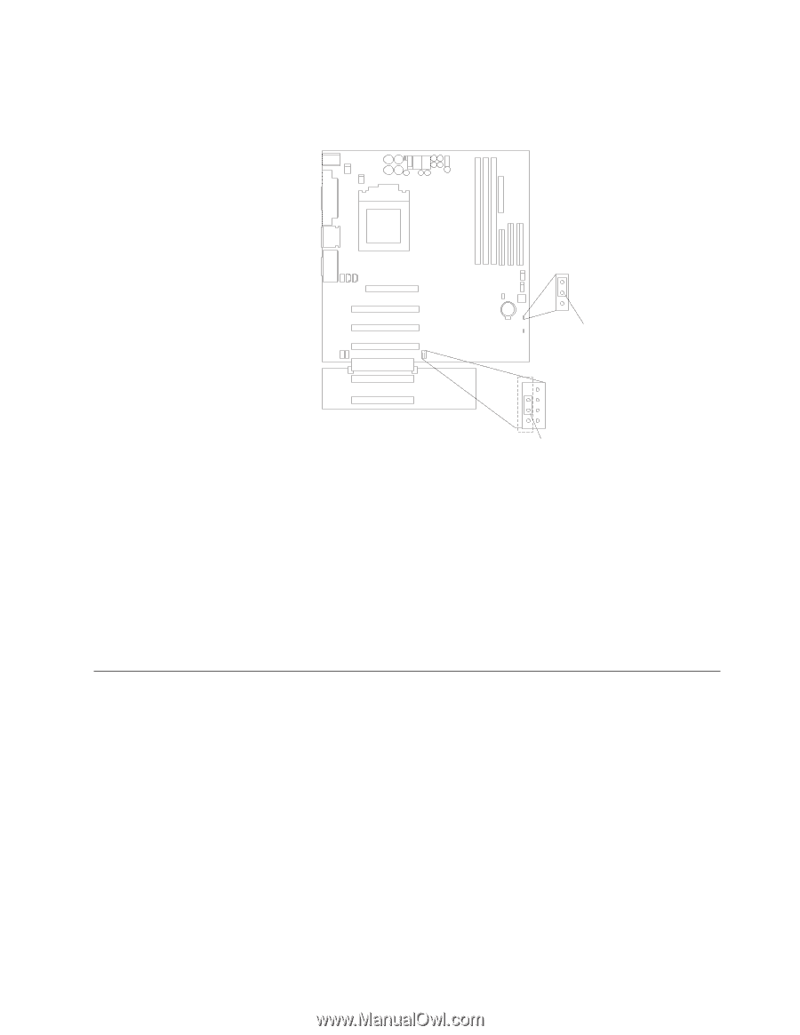
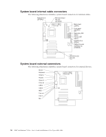
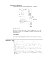
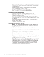
System board jumpers The following illustration identifies the jumpers on the system board. 1 2 3 CMOS jumper (JBAT1) 3 2 1 Boot block jumper (JROM1) Boot block jumper For normal operations of the system, a jumper is installed on pins 2 and 3 of the boot block jumper. See "Recovering BIOS" on page 99 for information about the boot block jumper. CMOS jumper For normal operation of the system, a jumper is installed on pins 1 and 2 of the CMOS jumper. See "Clearing CMOS" on page 103 for information about the CMOS jumper. Before you begin Before you begin to install options in your computer, read the following information. v Become familiar with the safety and handling guidelines specified under "Handling static-sensitive devices" on page 38, and read the safety statements in "Safety information" on page 39. These guidelines will help you work safely with your computer or options. v Make sure that you have an adequate number of properly grounded electrical outlets for your computer, monitor, and any other options that you intend to install. v When you need to access the inside of the computer to install options, you might find it easier to lay the computer on its side. If you do so, rotate the two front feet in towards the computer, so they do not break off due to the weight of the computer. Chapter 5. Installing options 37
-
 1
1 -
2
-
3
-
4
-
5
-
6
-
7
-
8
-
9
-
10
-
11
-
12
-
13
-
14
-
15
-
16
-
17
-
18
-
19
-
20
-
21
-
22
-
23
-
24
-
25
-
26
-
27
-
28
-
29
-
30
-
31
-
32
-
33
-
34
-
35
-
36
-
37
-
38
-
39
-
40
-
41
-
42
-
43
-
44
-
45
-
46
-
47
-
 48
48 -
 49
49 -
 50
50 -
 51
51 -
 52
52 -
 53
53 -
 54
54 -
 55
55 -
 56
56 -
 57
57 -
 58
58 -
59
-
60
-
61
-
62
-
63
-
64
-
65
-
66
-
67
-
68
-
69
-
70
-
71
-
72
-
73
-
74
-
75
-
76
-
77
-
78
-
79
-
80
-
81
-
82
-
83
-
84
-
85
-
86
-
87
-
88
-
89
-
90
-
91
-
92
-
93
-
94
-
95
-
96
-
97
-
98
-
99
-
100
-
101
-
102
-
103
-
104
-
105
-
106
-
107
-
108
-
109
-
110
-
111
-
112
-
113
-
114
-
115
-
116
-
117
-
118
-
119
-
120
-
121
-
122
-
123
-
124
-
125
-
126
-
127
-
128
-
129
-
130
-
131
-
132
-
133
-
134
-
135
-
136
-
137
-
138
-
139
-
140
-
141
-
142
-
143
-
144
-
145
-
146
-
147
-
148
-
149
-
150
-
151
-
152
-
153
-
154
-
155
-
156
 |
 |