Lenovo NetVista X40 Quick Reference for NetVista 2179 and 6643 systems (Dutch) - Page 68
Preinstallation steps (all bays), Installing a drive in bay 2 or 4
 |
View all Lenovo NetVista X40 manuals
Add to My Manuals
Save this manual to your list of manuals |
Page 68 highlights
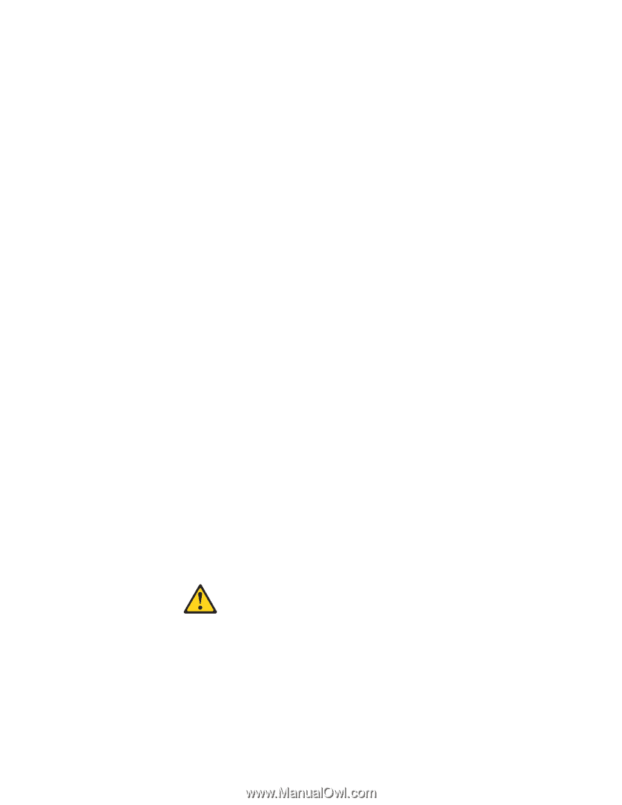
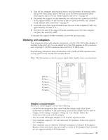
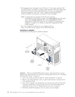
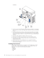
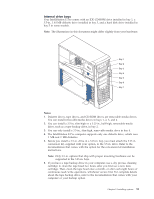
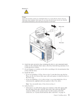
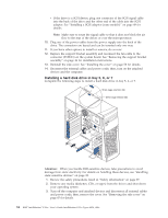
7. The electromagnetic interference (EMI) integrity and cooling of the computer are both protected by having bays 1 through 4 covered or occupied. When you install a drive, save the EMC shield and filler panel from the bay, in case you later remove the drive and do not replace it with another. 8. For a list of supported options for your computer, refer to http://www.ibm.com/pc/support on the World Wide Web. Preinstallation steps (all bays) Before you install drives in your computer, verify that you have all the cables and other equipment specified in the documentation that comes with the drive. You might also need to perform certain preinstallation activities. Some of the steps are required only during the initial installation of an option. 1. Read "Safety" on page v, "Handling static-sensitive devices" on page 38, and the documentation that comes with your drive. 2. Choose the bay in which you want to install the drive. 3. Check the instructions that come with the drive to see if you need to set any switches or jumpers on the drive. If you are installing a SCSI device, be sure to set the SCSI ID for that device. Installing a drive in bay 2 or 4 Complete the following steps to install a drive in bay 2 or 4. Attention: When you handle ESD-sensitive devices, take precautions to avoid damage from static electricity. For more details on handling these devices, see "Handling static-sensitive devices" on page 38. 1. Review the safety precautions listed in "Safety information" on page 39. 2. Remove any media (diskettes, CDs, or tapes) from the drives and shut down your operating system. 3. Turn off the computer and attached devices and disconnect all external cables and power cords; then, remove the side cover. See "Removing the side cover" on page 45 for details. 4. Remove the support bracket assembly and disconnect the fan cable from the connector (SYSFA3) on the system board. See "Removing the support bracket assembly" on page 46 for removal instructions. 5. Use a screwdriver to gently pry the filler panel and EMC shield away from the computer. Note: If you are installing a drive that is a laser product, observe the following safety precaution: Statement 3 CAUTION: When laser products (such as CD-ROMs, DVD drives, fiber optic devices, or transmitters) are installed, note the following: v Do not remove the covers. Removing the covers of the laser product could result in exposure to hazardous laser radiation. There are no serviceable parts inside the device. v Use of controls or adjustments or performance of procedures other than those specified herein might result in hazardous radiation exposure. 52 IBM® IntelliStation® E Pro: User's Guide IntelliStation E Pro Types 6836, 6846
-
 1
1 -
2
-
3
-
4
-
5
-
6
-
7
-
8
-
9
-
10
-
11
-
12
-
13
-
14
-
15
-
16
-
17
-
18
-
19
-
20
-
21
-
22
-
23
-
24
-
25
-
26
-
27
-
28
-
29
-
30
-
31
-
32
-
33
-
34
-
35
-
36
-
37
-
38
-
39
-
40
-
41
-
42
-
43
-
44
-
45
-
46
-
47
-
48
-
49
-
50
-
51
-
52
-
53
-
54
-
55
-
56
-
57
-
58
-
59
-
60
-
61
-
62
-
 63
63 -
 64
64 -
 65
65 -
 66
66 -
 67
67 -
 68
68 -
 69
69 -
 70
70 -
 71
71 -
 72
72 -
 73
73 -
74
-
75
-
76
-
77
-
78
-
79
-
80
-
81
-
82
-
83
-
84
-
85
-
86
-
87
-
88
-
89
-
90
-
91
-
92
-
93
-
94
-
95
-
96
-
97
-
98
-
99
-
100
-
101
-
102
-
103
-
104
-
105
-
106
-
107
-
108
-
109
-
110
-
111
-
112
-
113
-
114
-
115
-
116
-
117
-
118
-
119
-
120
-
121
-
122
-
123
-
124
-
125
-
126
-
127
-
128
-
129
-
130
-
131
-
132
-
133
-
134
-
135
-
136
-
137
-
138
-
139
-
140
-
141
-
142
-
143
-
144
-
145
-
146
-
147
-
148
-
149
-
150
-
151
-
152
-
153
-
154
-
155
-
156
 |
 |