Lenovo NetVista X40 Quick Reference for NetVista 2179 and 6643 systems (Dutch) - Page 69
Statement 3, Danger, You can install only a 3.5-in. device in bay 4.
 |
View all Lenovo NetVista X40 manuals
Add to My Manuals
Save this manual to your list of manuals |
Page 69 highlights
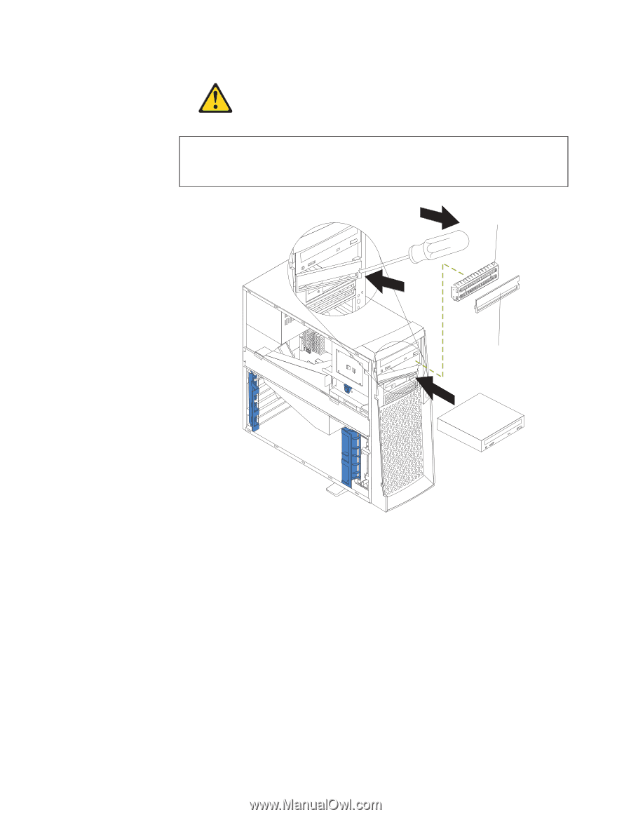
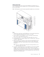
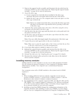
Statement 3 Danger Some laser products contain an embedded Class 3A or Class 3B laser diode. Note the following. Laser radiation when open. Do not stare into the beam, do not view directly with optical instruments, and avoid direct exposure to the beam. EMC shield Filler panel 6. Touch the static-protective bag containing the drive to any unpainted metal surface on the computer; then, remove the drive from the bag and place it on a static-protective surface. 7. Set any jumpers or switches on the drive according to the documentation that comes with the drive. 8. Install the drive: v If you are installing a 5.25-in. drive in bay 2, push the drive into the bay. Then, use the two screws that come with your option to attach the drive to the drive cage. v If you are installing a 3.5-in. drive in bay 2, you must attach the 5.25-in. conversion kit, supplied with your option, to the 3.5-in. drive. Note: You can install only a 3.5-in. device in bay 4. 9. Cable the drive: v If the drive is an IDE device, plug one connector of the IDE signal cable into the back of the drive and the other end of the cable into the IDE connector (IDE1) on the system board. For the location of the IDE connectors, see "System board internal cable connectors" on page 36. Chapter 5. Installing options 53
-
 1
1 -
2
-
3
-
4
-
5
-
6
-
7
-
8
-
9
-
10
-
11
-
12
-
13
-
14
-
15
-
16
-
17
-
18
-
19
-
20
-
21
-
22
-
23
-
24
-
25
-
26
-
27
-
28
-
29
-
30
-
31
-
32
-
33
-
34
-
35
-
36
-
37
-
38
-
39
-
40
-
41
-
42
-
43
-
44
-
45
-
46
-
47
-
48
-
49
-
50
-
51
-
52
-
53
-
54
-
55
-
56
-
57
-
58
-
59
-
60
-
61
-
62
-
63
-
 64
64 -
 65
65 -
 66
66 -
 67
67 -
 68
68 -
 69
69 -
 70
70 -
 71
71 -
 72
72 -
 73
73 -
 74
74 -
75
-
76
-
77
-
78
-
79
-
80
-
81
-
82
-
83
-
84
-
85
-
86
-
87
-
88
-
89
-
90
-
91
-
92
-
93
-
94
-
95
-
96
-
97
-
98
-
99
-
100
-
101
-
102
-
103
-
104
-
105
-
106
-
107
-
108
-
109
-
110
-
111
-
112
-
113
-
114
-
115
-
116
-
117
-
118
-
119
-
120
-
121
-
122
-
123
-
124
-
125
-
126
-
127
-
128
-
129
-
130
-
131
-
132
-
133
-
134
-
135
-
136
-
137
-
138
-
139
-
140
-
141
-
142
-
143
-
144
-
145
-
146
-
147
-
148
-
149
-
150
-
151
-
152
-
153
-
154
-
155
-
156
 |
 |