Lenovo NetVista X40 Quick Reference for NetVista 2179 and 6643 systems (Dutch) - Page 73
Installing a security U-bolt, No. 3230, Stock No. 176-735
 |
View all Lenovo NetVista X40 manuals
Add to My Manuals
Save this manual to your list of manuals |
Page 73 highlights
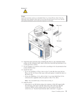
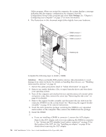
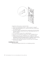
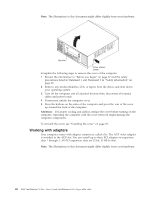
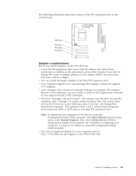
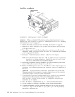
b. Open the retaining clip on each end of the DIMM slot. Turn the DIMM so that the pins align correctly with the connector. Note: To avoid breaking the retaining clips or damaging the DIMM connectors, open and close the clips gently. c. Insert the DIMM into the connector by aligning the DIMM edges with the slots at each end of the DIMM connector. Firmly press the DIMM straight down into the connector by applying pressure on both ends of the DIMM simultaneously. Be sure that the retaining clips snap into the locked position when the DIMM is firmly seated in the connector. d. If a gap exists between the DIMM and the retaining clips, the DIMM has not been correctly installed. In this case, open the retaining clips and remove the DIMM; then, reinsert the DIMM. e. If you removed the AGP adapter, reinstall it now. See "Installing an adapter" on page 48 for details. 8. If you have other options to install or remove, do so now. 9. Replace the support bracket assembly and reconnect the fan cable to the connector (SYSFA3) on the system board. See "Removing the support bracket assembly" on page 46 for installation instructions. 10. Reinstall the side cover. See "Installing the cover" on page 58 for details. 11. Reconnect the external cables and power cords; then, turn on the attached devices and the computer. If you want to remove a DIMM, reverse the previous steps. Installing a security U-bolt To help prevent hardware theft, you can add a security U-bolt and cable to your computer. After you add the security cable, make sure that it does not interfere with other cables that are connected to the computer. Before you begin: v Obtain the following items: - A flat-blade screwdriver - An adjustable wrench - A 199 mm (3/4 in.) U-bolt or wire rope (similar to National Manufacturing No. 3230, Stock No. 176-735) - Threaded nuts that fit the U-Bolt - A security cable - A lock, such as a combination lock or padlock. v Read the information in "Handling static-sensitive devices" on page 38, and "Safety information" on page 39. Chapter 5. Installing options 57
-
 1
1 -
2
-
3
-
4
-
5
-
6
-
7
-
8
-
9
-
10
-
11
-
12
-
13
-
14
-
15
-
16
-
17
-
18
-
19
-
20
-
21
-
22
-
23
-
24
-
25
-
26
-
27
-
28
-
29
-
30
-
31
-
32
-
33
-
34
-
35
-
36
-
37
-
38
-
39
-
40
-
41
-
42
-
43
-
44
-
45
-
46
-
47
-
48
-
49
-
50
-
51
-
52
-
53
-
54
-
55
-
56
-
57
-
58
-
59
-
60
-
61
-
62
-
63
-
64
-
65
-
66
-
67
-
 68
68 -
 69
69 -
 70
70 -
 71
71 -
 72
72 -
 73
73 -
 74
74 -
 75
75 -
 76
76 -
 77
77 -
 78
78 -
79
-
80
-
81
-
82
-
83
-
84
-
85
-
86
-
87
-
88
-
89
-
90
-
91
-
92
-
93
-
94
-
95
-
96
-
97
-
98
-
99
-
100
-
101
-
102
-
103
-
104
-
105
-
106
-
107
-
108
-
109
-
110
-
111
-
112
-
113
-
114
-
115
-
116
-
117
-
118
-
119
-
120
-
121
-
122
-
123
-
124
-
125
-
126
-
127
-
128
-
129
-
130
-
131
-
132
-
133
-
134
-
135
-
136
-
137
-
138
-
139
-
140
-
141
-
142
-
143
-
144
-
145
-
146
-
147
-
148
-
149
-
150
-
151
-
152
-
153
-
154
-
155
-
156
 |
 |