Lenovo NetVista X40 Quick Reference for NetVista 2179 and 6643 systems (Dutch) - Page 82
into the back of the drive and the other end of the cable into the IDE
 |
View all Lenovo NetVista X40 manuals
Add to My Manuals
Save this manual to your list of manuals |
Page 82 highlights
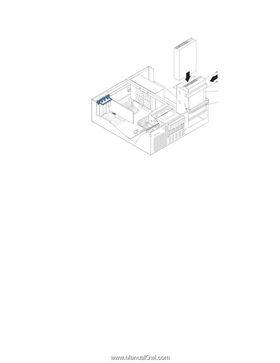
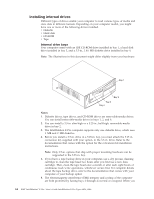
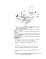
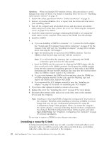
Drive cage Drive cage latch Note: If your computer has a CD-ROM drive installed in bay 1, remove the signal and power cables from the CD-ROM drive before rotating the drive cage out of the computer. 5. Rotate the drive cage toward the front of the computer until the drive cage latch locks on the chassis. Attention: Do not use the drive cage latch to rotate either drive cage out of the computer. 6. Touch the static-protective bag containing the drive to any unpainted metal surface on the computer; then, remove the drive from the bag and place it on a static-protective surface. 7. Set any jumpers or switches on the drive according to the documentation that comes with the drive. 8. Install the drive: v If you are installing a 5.25-in. drive in bay 2, push the drive in to the bay; then, use the two screws to attach the drive to the drive cage. v If you are installing a 3.5-in. drive in bay 2, you must attach the 5.25-in. conversion kit, supplied with your option, to the 3.5-in. drive. 9. Cable the drive: v If the drive is an IDE device, plug one connector of the IDE signal cable into the back of the drive and the other end of the cable into the IDE connector (IDE1) on the system board. For the location of the IDE connectors, see "System board internal cable connectors" on page 36. v If the drive is a SCSI device, plug one connector of the SCSI signal cable into the back of the drive and the other end of the cable into the SCSI adapter. Note: Make sure to route the cable so that it does not block the air flow to the rear of the drives or over the microprocessor. 66 IBM® IntelliStation® E Pro: User's Guide IntelliStation E Pro Types 6836, 6846
-
 1
1 -
2
-
3
-
4
-
5
-
6
-
7
-
8
-
9
-
10
-
11
-
12
-
13
-
14
-
15
-
16
-
17
-
18
-
19
-
20
-
21
-
22
-
23
-
24
-
25
-
26
-
27
-
28
-
29
-
30
-
31
-
32
-
33
-
34
-
35
-
36
-
37
-
38
-
39
-
40
-
41
-
42
-
43
-
44
-
45
-
46
-
47
-
48
-
49
-
50
-
51
-
52
-
53
-
54
-
55
-
56
-
57
-
58
-
59
-
60
-
61
-
62
-
63
-
64
-
65
-
66
-
67
-
68
-
69
-
70
-
71
-
72
-
73
-
74
-
75
-
76
-
 77
77 -
 78
78 -
 79
79 -
 80
80 -
 81
81 -
 82
82 -
 83
83 -
 84
84 -
 85
85 -
 86
86 -
 87
87 -
88
-
89
-
90
-
91
-
92
-
93
-
94
-
95
-
96
-
97
-
98
-
99
-
100
-
101
-
102
-
103
-
104
-
105
-
106
-
107
-
108
-
109
-
110
-
111
-
112
-
113
-
114
-
115
-
116
-
117
-
118
-
119
-
120
-
121
-
122
-
123
-
124
-
125
-
126
-
127
-
128
-
129
-
130
-
131
-
132
-
133
-
134
-
135
-
136
-
137
-
138
-
139
-
140
-
141
-
142
-
143
-
144
-
145
-
146
-
147
-
148
-
149
-
150
-
151
-
152
-
153
-
154
-
155
-
156
 |
 |