Lenovo NetVista X40 Quick Reference for NetVista 2179 and 6643 systems (Dutch) - Page 63
Working with adapters, Adapter considerations
 |
View all Lenovo NetVista X40 manuals
Add to My Manuals
Save this manual to your list of manuals |
Page 63 highlights
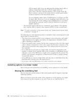
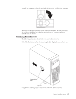
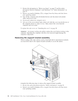
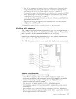
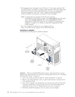
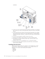
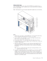
3. Turn off the computer and attached devices and disconnect all external cables and power cords; then, remove the side cover. For more information about removing the side cover, see "Removing the side cover" on page 45. 4. Disconnect the support bracket assembly fan cable from the connector (SYSFA3) on the system board. For the location of the fan cable connector, see "System board internal cable connectors" on page 36. 5. Locate the end of the support bracket near the rear of the computer. Pull it out approximately 152 mm (6 in.). 6. Pull the front end of the support bracket assembly away from the computer and place the assembly aside. To reinstall the support bracket assembly, reverse the previous steps. Working with adapters Your computer comes with adapter connectors, call slots. The AGP video adapter is installed in the AGP slot. You can install up to five PCI adapters in PCI expansion slots 1 through 5. All PCI expansion slots are 32-bit, 33 MHz slots. The following illustration shows the location of the AGP and PCI expansion slots on the system board and the PCI extender board. Note: The illustrations in this document might differ slightly from your hardware. AGP slot PCI slot 1 PCI slot 2 PCI slot 3 PCI slot 4 PCI slot 5 Adapter considerations Before you install adapters, review the following: v Locate the documentation that comes with the adapter and follow those instructions in addition to the instructions given in this chapter. If you need to change switch settings or jumper settings on your adapter, follow the instructions that come with the adapter. v You can install full-length adapters in all five PCI expansion slots. v Your computer supports 5.0 V and universal PCI adapters; it does not support 3.3 V adapters. v Your computer uses a rotational interrupt technique to configure PCI adapters. Because of this technique, you can install a variety of PCI adapters that currently do not support sharing of PCI interrupts. Chapter 5. Installing options 47
-
 1
1 -
2
-
3
-
4
-
5
-
6
-
7
-
8
-
9
-
10
-
11
-
12
-
13
-
14
-
15
-
16
-
17
-
18
-
19
-
20
-
21
-
22
-
23
-
24
-
25
-
26
-
27
-
28
-
29
-
30
-
31
-
32
-
33
-
34
-
35
-
36
-
37
-
38
-
39
-
40
-
41
-
42
-
43
-
44
-
45
-
46
-
47
-
48
-
49
-
50
-
51
-
52
-
53
-
54
-
55
-
56
-
57
-
 58
58 -
 59
59 -
 60
60 -
 61
61 -
 62
62 -
 63
63 -
 64
64 -
 65
65 -
 66
66 -
 67
67 -
 68
68 -
69
-
70
-
71
-
72
-
73
-
74
-
75
-
76
-
77
-
78
-
79
-
80
-
81
-
82
-
83
-
84
-
85
-
86
-
87
-
88
-
89
-
90
-
91
-
92
-
93
-
94
-
95
-
96
-
97
-
98
-
99
-
100
-
101
-
102
-
103
-
104
-
105
-
106
-
107
-
108
-
109
-
110
-
111
-
112
-
113
-
114
-
115
-
116
-
117
-
118
-
119
-
120
-
121
-
122
-
123
-
124
-
125
-
126
-
127
-
128
-
129
-
130
-
131
-
132
-
133
-
134
-
135
-
136
-
137
-
138
-
139
-
140
-
141
-
142
-
143
-
144
-
145
-
146
-
147
-
148
-
149
-
150
-
151
-
152
-
153
-
154
-
155
-
156
 |
 |