Netgear SRXN3205 SRXN3205 Reference Manual - Page 172
Community, Administration > SNMP, Create New SNMP Configuration Entry, IP Address, Subnet Mask
 |
UPC - 606449057461
View all Netgear SRXN3205 manuals
Add to My Manuals
Save this manual to your list of manuals |
Page 172 highlights
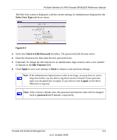
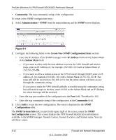
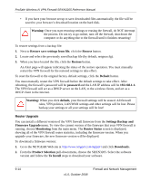
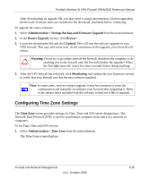
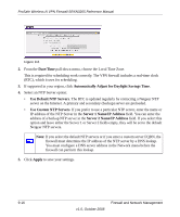
ProSafe Wireless-N VPN Firewall SRXN3205 Reference Manual • Community. The trap community string of the configuration. To create a new SNMP configuration entry: 1. Select Administration > SNMP from the main/submenu and the SNMP screen displays. . Figure 9-4 2. Configure the following fields in the Create New SNMP Configuration Entry section: • Enter the IP Address of the SNMP manager in the IP Address field and the Subnet Mask in the Subnet Mask field. - If you want to allow only the host address to access the VPN firewall and receive traps, enter an IP Address of, for example, 192.168.1.101 with a Subnet Mask of 255.255.255.255. - If you want to allow a subnet access to the VPN firewall through SNMP, enter an IP address of, for example,192.168.1.101 with a Subnet Mask of 255.255.255.0. The traps will still be received on 192.168.1.101, but the entire subnet will have access through the community string. - If you want to make the VPN firewall globally accessible using the community string, but still receive traps on the host, enter 0.0.0.0 as the Subnet Mask and an IP Address for where the traps will be received. • Enter the trap port number of the configuration in the Port field. The default is 162. • Enter the trap community string of the configuration in the Community field. 3. Click Add to create the new configuration. The entry is displayed in the SNMP Configuration table. The SNMP System Info link, located in the upper right of the screen, opens the SNMP SysConfiguration screen. This screen displays the VPN firewall identification information available to the SNMP manager: System Contact, System Location, and System name. You can edit these values. 9-12 v1.0, October 2008 Firewall and Network Management
-
 1
1 -
2
-
3
-
4
-
5
-
6
-
7
-
8
-
9
-
10
-
11
-
12
-
13
-
14
-
15
-
16
-
17
-
18
-
19
-
20
-
21
-
22
-
23
-
24
-
25
-
26
-
27
-
28
-
29
-
30
-
31
-
32
-
33
-
34
-
35
-
36
-
37
-
38
-
39
-
40
-
41
-
42
-
43
-
44
-
45
-
46
-
47
-
48
-
49
-
50
-
51
-
52
-
53
-
54
-
55
-
56
-
57
-
58
-
59
-
60
-
61
-
62
-
63
-
64
-
65
-
66
-
67
-
68
-
69
-
70
-
71
-
72
-
73
-
74
-
75
-
76
-
77
-
78
-
79
-
80
-
81
-
82
-
83
-
84
-
85
-
86
-
87
-
88
-
89
-
90
-
91
-
92
-
93
-
94
-
95
-
96
-
97
-
98
-
99
-
100
-
101
-
102
-
103
-
104
-
105
-
106
-
107
-
108
-
109
-
110
-
111
-
112
-
113
-
114
-
115
-
116
-
117
-
118
-
119
-
120
-
121
-
122
-
123
-
124
-
125
-
126
-
127
-
128
-
129
-
130
-
131
-
132
-
133
-
134
-
135
-
136
-
137
-
138
-
139
-
140
-
141
-
142
-
143
-
144
-
145
-
146
-
147
-
148
-
149
-
150
-
151
-
152
-
153
-
154
-
155
-
156
-
157
-
158
-
159
-
160
-
161
-
162
-
163
-
164
-
165
-
166
-
 167
167 -
 168
168 -
 169
169 -
 170
170 -
 171
171 -
 172
172 -
 173
173 -
 174
174 -
 175
175 -
 176
176 -
 177
177 -
178
-
179
-
180
-
181
-
182
-
183
-
184
-
185
-
186
-
187
-
188
-
189
-
190
-
191
-
192
-
193
-
194
-
195
-
196
-
197
-
198
-
199
-
200
-
201
-
202
-
203
-
204
-
205
-
206
-
207
-
208
-
209
-
210
-
211
-
212
-
213
-
214
-
215
-
216
-
217
-
218
 |
 |
