Icom IC-2820H Instruction Manual
Icom IC-2820H Manual
 |
View all Icom IC-2820H manuals
Add to My Manuals
Save this manual to your list of manuals |
Icom IC-2820H manual content summary:
- Icom IC-2820H | Instruction Manual - Page 1
INSTRUCTION MANUAL DUAL BAND FM TRANSCEIVER i2820H This device complies with Part 15 of the FCC Rules. Operation is subject to the following two conditions: (1) this device may not cause harmful interference, and (2) this device must accept any interference received, including interference that may - Icom IC-2820H | Instruction Manual - Page 2
The IC-2820H DUAL BAND FM TRANSCEIVER is designed and built with Icom's superior technology and craftsmanship. With proper care, this product should provide you with years of trouble-free operation. We want to take a couple of moments of your time to thank you for making your IC-2820H your radio of - Icom IC-2820H | Instruction Manual - Page 3
FCC Guidelines for Human Radio frequency Electromagnetic Fields (OET Bulletin 65). RWARNING! NEVER connect the transceiver to an AC out- the transceiver. NEVER connect the transceiver to a power source using reverse polarity. This will damage the transceiver. NEVER cut the DC power cable between - Icom IC-2820H | Instruction Manual - Page 4
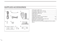
SUPPLIED ACCESSORIES q w r e t y u i o !0 q DC power cable (3 m 1 w Controller cable (10 cm†; 3.9 in 1 e Separation cable (3.4 m†; 11.2 ft 1 r Microphone (HM-133 1 t Fuse (20 A 1 y Microphone hanger 1 u Mounting screws, nuts and washers 1 set i Mobile mounting bracket 1 o - Icom IC-2820H | Instruction Manual - Page 5
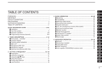
ACCESSORIES iii TABLE OF CONTENTS iv QUICK REFERENCE GUIDE I-XIV ■ Installation I ■ Your first contact X ■ Repeater operation XII ■ Programming band mute/busy beep 24 ■ Monitor function 24 7 ■ Single band operation 25 8 ■ One-touch PTT function 26 ■ Audio mute function 27 9 ■ Band - Icom IC-2820H | Instruction Manual - Page 6
CONTENTS 5 DV MODE OPERATION (Optional UT-123 is required) ..... 36-60 ■ Digital mode operation 36 ■ Call sign programming 36 ■ Digital voice mode operation 39 ■ About D-STAR system 41 ■ Digital repeater operation 42 ■ Received call sign 47 ■ Copying the call sign 49 ■ Break-in communication - Icom IC-2820H | Instruction Manual - Page 7
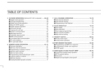
PAGER/CODE SQUELCH 92-95 ■ Pager function 92 ■ Code programming 92 ■ Pager operation 94 ■ Code squelch 95 13 version only 123 8 16 GPS/GPS-A OPERATION 125-132 9 ■ GPS operation 125 ■ GPS-A operation 132 10 17 MAINTENANCE 133-135 11 ■ Troubleshooting 133 ■ Fuse replacement 134 - Icom IC-2820H | Instruction Manual - Page 8
GUIDE ■ Installation D Precaution- magnets RCAUTION Magnets are used for the controller's attachment to the main unit. NEVER hold the whole unit by the controller only when carrying the transceiver. Carry the transceiver type), magnetic compass and any magnetic/IC cards, credit cards, etc. It may - Icom IC-2820H | Instruction Manual - Page 9
16.4 ft) is available to extend the microphone cable. • Optional OPC-441 SPEAKER CABLE (5.0 m; 16.4 ft) is available to extend the speaker cable. D Location Select a location which can support the weight of the transceiver and does not interfere with driving. We recommend the locations shown in the - Icom IC-2820H | Instruction Manual - Page 10
QUICK REFERENCE GUIDE D Using the mounting bracket qDrill 4 holes where the mounting bracket Separation cable connection Two connection cables, controller cable (10 cm; 3.9 in) for single body installation and separation cable (3.4 m; 11.2 ft) for remote installation, are supplied with the IC-2820H - Icom IC-2820H | Instruction Manual - Page 11
connection, otherwise the controller will separate from the main unit when the microphone cable is pulled during single body installation. to [GPS ANT] GPS antenna cable length: approx. 5 m (16.4 ft) Mount the GPS antenna onto a convenient flat surface. The GPS antenna includes magnet mount base - Icom IC-2820H | Instruction Manual - Page 12
3. Under a bridge or viaduct 4. In remote forested areas 5. Under bad weather condition (rainy or cloudy day) V D Controller's attachment You can attach the controller of the IC-2820H by one of 2 methods. • Example 1 • Example 2 - Icom IC-2820H | Instruction Manual - Page 13
Quick reference guide QUICK REFERENCE GUIDE D Remote installation The supplied remote controller bracket is used for remote in- stallation. • Attach the remote controller bracket onto a flat surface These screws are not - Icom IC-2820H | Instruction Manual - Page 14
the transceiver directly to a 24 V battery. ➥ DO NOT use the cigarette lighter socket for power con- nections. (See p. 10 for details) Use a rubber grommet when passing the DC power cable through a metal plate to prevent a short circuit. • CONNECTING TO A DC POWER SOURCE Grommet IC-2820H _ black - Icom IC-2820H | Instruction Manual - Page 15
at least 15 A capacity. Make sure the ground terminal of the DC power supply is grounded. • CONNECTING TO A DC POWER SUPPLY to an AC outlet IC-2820H DC power supply 13.8 V −⊕ − black ⊕ red See p. 134 for fuse replacement. Fuses 20 A QUICK REFERENCE - Icom IC-2820H | Instruction Manual - Page 16
QUICK REFERENCE GUIDE D Antenna installation • Antenna location To obtain maximum performance from the transceiver, select a high- solder 1-2 mm q Slide the coupling ring down. Strip the cable jacket and tin. w Strip the cable as shown at left. Soft solder the center conductor. solder solder - Icom IC-2820H | Instruction Manual - Page 17
reference guide ■ Your first contact Now that you have your IC-2820H installed in your car or shack, you are probably anxious to get on the air. We would like to take you through a few basic operation steps to make your first time "On The Air" an enjoyable experience. 1. Turning ON the transceiver - Icom IC-2820H | Instruction Manual - Page 18
IC-2820H can use 2 m or 70 cm on either the left or right band. The operating band can be exchanged between them, and using the same bands, V/V and U/U, is also possible.. 4. Tune the frequency The tuning dial will allow you to dial in the frequency you want to use. Pages 17 and 18 will instruct - Icom IC-2820H | Instruction Manual - Page 19
Quick reference guide QUICK REFERENCE GUIDE ■ Repeater operation 1. Setting duplex Push the desired band's [MAIN•BAND] to select the main band. Push [DUP•MONI] once or twice to select minus duplex or plus duplex. • The USA version has an auto repeater function, therefore, setting duplex is - Icom IC-2820H | Instruction Manual - Page 20
QUICK REFERENCE GUIDE ■ Programming memory channels The IC-2820H has a total of 522 memory channels (including 20 scan edge and 2 call channels) for storing often used operating frequency, repeater settings, etc. Any memory channel can be recalled on either the left or right band. 1. Setting a - Icom IC-2820H | Instruction Manual - Page 21
. • Set other data, such as repeater tone, duplex information, tun- ing step, if necessary. rPush [FUNC] then push and hold [CLR A(MW)] for 1 sec. to program. Push , then • 3 beeps sound • Memory channel number automatically increases when continu- ing to push [CLR A(MW)] after - Icom IC-2820H | Instruction Manual - Page 22
DESCRIPTION ■ Front panel- controller Function display (pgs. 3-8) q DUAL BAND TRANSCEIVER i2820H w N BAN N BAN D D M AI M AI *The keys w to t are for V/MHz SCAN M/CALL MW DUP MONI TONE DTMF LOW PRIO M/CALL MW V/MHz SCAN the MAIN band only. tr e q POWER KEY [PWR] Push and hold - Icom IC-2820H | Instruction Manual - Page 23
band Right band 1 y DUAL BAND TRANSCEIVER i2820H 2 y 3 u u 4 5 N BAN N BAN i D D i 6 MA M AI V/MHz M/CALL DUP TONE LOW M/CALL V/MHz 7 SCAN MW MONI DTMF PRIO MW SCAN 8 *The same controls for both the left and right bands programming. (pgs. 62, 73, 76) 18 19 2 - Icom IC-2820H | Instruction Manual - Page 24
bands are arranged. q OPERATING MODE INDICATOR (p. 21) Shows the selected operating mode. • FM, FM-N, AM, AM-N and DV* are available, depending on operating band memory mode operation, the programmed memory or memory bank name is displayed. r TONE INDICATOR ➥ During FM mode operation: ● "TONE - Icom IC-2820H | Instruction Manual - Page 25
GPS INDICATOR (p. 126) Appears while GPS function* is in use. *Available only when the optional UT-123 is installed. u SUB BAND REMOTE CONTROL INDICATOR (p. 96) Appears when the sub band when the displayed frequency is specified 12 as a program skip frequency. 13 !6 MEMORY INDICATOR (p. 61) Appears - Icom IC-2820H | Instruction Manual - Page 26
output power; "MID" appears when middle output power, "HI" appears when high output power is selected. @2 MAIN INDICATOR (p. 15) Indicates the main band for transmit and function control. @0 BUSY INDICATOR ➥ Appears when a signal is being received or the squelch is open. (p. 20) ➥ Blinks while the - Icom IC-2820H | Instruction Manual - Page 27
@4 @5 Function guide indications (pgs. 7, 8) @3 FREQUENCY MARKER (p. 27) Gap shows the selected frequency in the band scope. @4 CENTER FREQUENCY MARKER Dotted line shows the center frequency of the band scope. @5 BAND SCOPE INDICATOR When the band scope function is in use, shows the band conditions - Icom IC-2820H | Instruction Manual - Page 28
indications allow you to simply using a wide variety of functions. D Function guide q w e r t y u q MODE KEY [MODE](V/MHz•SCAN) (p. 21) Push to select an operating mode from FM, FM-N, AM, AM-N and DV* in main band. *Available only when the optional UT-123 is installed. w TUNING STEP KEY - Icom IC-2820H | Instruction Manual - Page 29
[REC](V/MHz•SCAN) (p. 58) Push to display the DV voice memory record screen. 1 D Function guide 3 2 The function guide 3 indications appear only when the op- 3 tional UT-123 is installed and GPS function is set to ON. 4 5 !4 !5 !6 !7 !8 u 6 7 !4 DATA KEY [DATA](V/MHz•SCAN) (p. 127) Push to - Icom IC-2820H | Instruction Manual - Page 30
] (p. III) Connects the controller unit with the supplied controller or separation cable. w DATA JACK [DATA] (p. 57) Connect to a PC via the optional data communication cable OPC-1529R for data cloning with the optional cloning software, CS-2820, or low-speed data communication in DV* mode operation - Icom IC-2820H | Instruction Manual - Page 31
cable for diversity reception. o EXTERNAL SPEAKER JACK 1 [SP-1] Connects an 8 Ω speaker. Outputs audio from both left and right bands transceiver but also lead to TVI or BCI problems. 6 7 !0 EXTERNAL SPEAKER JACK 2 [SP-2] • Speaker information 8 Connects an 8 Ω speaker. Outputs right band - Icom IC-2820H | Instruction Manual - Page 32
FUNCTION KEY [FUNC] i DTMF SELECT KEY [DTMF-S] (p. 84) o FUNCTION KEYS [F-1]/[F-2] (p. 115) Program and recall your desired transceiver configuration. !0 BAND KEY [BAND] (p. 15) Push to select main band between left and right bands. !1 MEMORY/CALL KEY [MR/CALL] ➥ Push to select memory mode. (p. 61 - Icom IC-2820H | Instruction Manual - Page 33
keypad 1 KEY FUNCTION SECONDARY FUNCTION ( +key) OTHER FUNCTIONS 2 Switches between opening and closing the In VFO mode enters operating band selec- 3 squelch. (p. 24) tion. 4 In memory mode enters bank selection. 5 (p. 64) Starts and stops scanning. (p. 75) Starts and stops - Icom IC-2820H | Instruction Manual - Page 34
1 PANEL DESCRIPTION KEY FUNCTION SECONDARY FUNCTION ( +key) OTHER FUNCTIONS ➥ Cancels frequency entry. (p. 17) ➥ Stores the set frequency, etc., into the ➥ Cancels the scan or priority watch. selected memory channel when pushed (pgs. 75, 81) and held. (p. 63) ➥ Exit set mode. (p. 98) ➥ - Icom IC-2820H | Instruction Manual - Page 35
■ Optional Microphone (HM-154) w ON q e OFF q PTT SWITCH Push and hold to transmit; release to receive. w UP/DOWN KEYS [UP]/[DN] ➥ Push either key to change operating frequency, memory channel, set mode setting, etc. (pgs. 17, 61, 98) ➥ Push and hold either key for 1 sec. to start scanning. (p. - Icom IC-2820H | Instruction Manual - Page 36
D MAIN band The IC-2820H can receive 144 MHz and 440(430) MHz band signals simultaneously. To change or activate any of the functions or to change frequency via the microphone, you must designate one band as the main band. The transceiver transmits a signal on the main band only. [MAIN•BAND] ➥ Push - Icom IC-2820H | Instruction Manual - Page 37
versions only In addition to the 2 m and 70 cm ham bands, the IC-2820H USA and General versions have extra frequency bands for each left and right bands as follow. See the specifications for the available frequency bands for details. Frequency band initial* 127 136 146 222 375 440 500 900 Left - Icom IC-2820H | Instruction Manual - Page 38
cancel it. ■ Using the keypad The frequency can be directly set via numeral keys on the mi- crophone. z Push [BAND] to select the desired band (left or ENT right) as the main band. C • Push [VFO/LOCK] to select VFO mode, if necessary. x Push [ENT C(T-OFF)] to activate the keypad for digit - Icom IC-2820H | Instruction Manual - Page 39
[V/MHz•SCAN] to select VFO mode, if necessary. w Push [F• ] to display the function guide. [F• ] [TS] 1 ePush [TS](M/CALL•MW) (Left band's) to enter tuning step 2 set mode. 3 4 5 6 7 rRotate the same band's [DIAL] to select the desired tuning step. 8 tPush [F• ] to exit tuning step set - Icom IC-2820H | Instruction Manual - Page 40
to turn 16KEY-L the microphone keypad lock function ON and OFF. • [PTT], [VFO/LOCK], [MR/CALL], [BAND], [Y], [Z], [F-1], [F-2], [DTMF-S] and [FUNC] on the microphone can be used. • All keys on the transceiver can be used. • The keypad lock function is released when the power is turned OFF then ON - Icom IC-2820H | Instruction Manual - Page 41
Rotate the main band's [SQL] fully counterclockwise in advance, then rotate the [SQL] clockwise until the noise just disappears. • When interference due to The IC-2820H is equipped with protection circuits to protect 16 the power amplifier circuit from high temperature. When the transceiver - Icom IC-2820H | Instruction Manual - Page 42
radio signals. The transceiver has total 5 operating modes (FM, FM-N, AM, AM-N and DV* modes). The mode selection is stored independently for each band guide. wPush [MODE](V/MHz•SCAN) (Left band's) several times to select the desired operating mode from FM, FM-N, AM, AM-N and DV* in main band. - Icom IC-2820H | Instruction Manual - Page 43
BASIC OPERATION 3 ■ Squelch attenuator The transceiver has an RF attenuator related to the monitor function. 1 D Squelch attenuator setting 2 q Push [F• ] to display the function guide. w Push [MENU](V/MHz•SCAN) (Right band's) to enter MENU 3 screen. 4 5 [F• ] 6 [MENU] 7 eRotate [DIAL] - Icom IC-2820H | Instruction Manual - Page 44
3 BASIC OPERATION ■ V/V, U/U simultaneous receive (Para-watch) The IC-2820H can simultaneously receive two signals on the same band, such as 144 MHz band, using the para-watch function. To activate the para-watch function from the HM-133, enter the desired frequencies for each the left and right - Icom IC-2820H | Instruction Manual - Page 45
the function guide. w Push [MENU](V/MHz•SCAN) (Right band's) to enter MENU screen. eRotate [DIAL] to select "SOUNDS" then push [MAIN•BAND]. rRotate [DIAL] to select "SUB BAND MUTE" or "SUB BAND BEEP" then push [MAIN•BAND]. tRotate [DIAL] to turn the sub band mute or sub band beep function - Icom IC-2820H | Instruction Manual - Page 46
. The IC-2820H has two independent receiver circuits: left band, and right band (available frequencies, operating mode and functions are different depending on bands). Single band operation is useful when only one frequency is being watched. q Push [F• ] to display the function guide. w Push - Icom IC-2820H | Instruction Manual - Page 47
is selected; When a frequency band that the diversity reception is inhibited is selected. With the squelch open in FM mode while receiving a weak switch. 4 To prevent accidental, continuous transmissions with this 5 function, the transceiver has a time-out timer. See p. 101 for 6 details. 7 - Icom IC-2820H | Instruction Manual - Page 48
. About the sweep steps: The specified tuning step in each frequency band (in VFO mode) or programmed tuning step (in memory mode) is used during sweep. Sweep step indication " " indicators appear Band scope indication Frequency marker [F• ] [DIAL] Frequency marker [SCP] [CLR] [CENT] 27 - Icom IC-2820H | Instruction Manual - Page 49
starting from the center of the range. rTo stop sweeping, push [F• ] to display the function guide, then push [SCP](DUP•MONI). tPush [F• ] to display the function guide, then push [CLR](LOW•PRIO) to clear the band scope. The receive audio during sweeping can be muted in sounds set mode. See page 109 - Icom IC-2820H | Instruction Manual - Page 50
radio because a repeater has much higher output power than the typical transceiver. operation flow chart Step 1: Set the desired band to operate the repeater. Step 2: Set the - Set the subaudible tone frequency, if required. • The IC-2820H USA version has the auto repeater function. Thus the steps - Icom IC-2820H | Instruction Manual - Page 51
REPEATER OPERATION 4 ■ Accessing a repeater qSet the receive frequency (repeater output frequency) on the main band. (pgs. 15-17) wPush [DUP•MONI] one or two times, to select minus duplex or plus duplex. • "DUP-" or "DUP+" appears to indicate the transmit - Icom IC-2820H | Instruction Manual - Page 52
4 REPEATER OPERATION DUP- 7 DUP+ 8 z Set the receive frequency (repeater output frequency) on the main band. (pgs. 16, 17) x Push [DUP- 7(TONE)] to select minus duplex; push [DUP+ 8(TSQLS)] to select plus duplex. • "DUP-" or "DUP+" appears. Push Push c Push [FUNC] - Icom IC-2820H | Instruction Manual - Page 53
memory/call channel. w Push [F• ] to display the function guide. e Push [MENU](V/MHz•SCAN) (Right band's) to enter MENU screen. rRotate [DIAL] to select "DUP/TONE..." then push [MAIN•BAND]. tRotate [DIAL] to select "REPEATER TONE" then push [MAIN•BAND]. yRotate [DIAL] to select and set the desired - Icom IC-2820H | Instruction Manual - Page 54
(p. 83) • Push [DTMF-S] again to return the keypad to nor- mal function control. Push , then push desired keys. ✔ For your convenience! The transceiver has 16 DTMF memory channels for autopatch operation. See p. 82 for details. D 1750 Hz tone The microphone has 1750 Hz tone capability, used for - Icom IC-2820H | Instruction Manual - Page 55
the offset frequency for, such as VFO mode or memory/call channel. ePush [F• ] to display the function guide then push [MENU](V/MHz•SCAN) (Right band's) to enter MENU screen. rRotate [DIAL] to select "DUP/TONE...", then push [MAIN•BAND]. tRotate [DIAL] to select "OFFSET FREQ" item, then push [MAIN - Icom IC-2820H | Instruction Manual - Page 56
MHz "DUP-" appears • Korean version FREQUENCY RANGE 439.000-440.000 MHz SHIFT DIRECTION "DUP-" appears USA/KOREAN versions only q Push [F• ] to display the function guide. w Push [MENU](V/MHz•SCAN) (Right band's) to enter MENU screen. e Rotate [DIAL] to select "SET MODE" then push [MAIN - Icom IC-2820H | Instruction Manual - Page 57
The IC-2820H can be operated in digital voice mode and lowspeed data operation for both transmit and receive when the optional UT-123 is installed. Also, position data transmission and reception are available with the UT-123. A GPS antenna is supplied with the UT-123. ■ Call sign programming - Icom IC-2820H | Instruction Manual - Page 58
123 is required) D Your own call sign programming Your own call sign must be programmed for both digital voice and low-speed data communications (including GPS transmission). q Push [F• ] to display the function guide. w Push [MENU](V/MHz•SCAN) (Right band's) to enter MENU screen. eRotate [DIAL] to - Icom IC-2820H | Instruction Manual - Page 59
) D Station call sign programming Station call signs must be programmed for the specified station call as well as repeater operation in all digital voice, lowspeed data and GPS communications. q Push [F• ] to display the function guide. w Push [MENU](V/MHz•SCAN) (Right band's) to enter MENU screen - Icom IC-2820H | Instruction Manual - Page 60
function guide 2. xPush [CS](V/MHz•SCAN) (Left band's) to display call sign screen. NOTE: The digital mode operation is vastly different from FM mode. push [BACK](V/MHz•SCAN) (Right band's) to set "MY CALL SIGN." • See page 37 for your own call sign programming details. rSet the desired call sign - Icom IC-2820H | Instruction Manual - Page 61
• See page 38 for station call sign programming details. m Push [BACK](V/MHz•SCAN) (Right band's) to set the station's call sign and return to CALL SIGN screen. , Push [BACK](V/MHz•SCAN) (Right band's) again to return to function guide 2 indication. . Perform the instruction steps t to y on page 39 - Icom IC-2820H | Instruction Manual - Page 62
5 DV MODE OPERATION (Optional UT-123 is required) ■ About D-STAR system In the D-STAR system, repeater linking via a 10 GHz band backbone and internet network (gateway connection) capabilities are available. This system provides you with much wider coverage range during digital voice mode operation - Icom IC-2820H | Instruction Manual - Page 63
voice and low-speed data communications. D Repeater call sign programming q Push [F• ] to display the function guide. w Push [MENU](V/MHz•SCAN) (Right band's) to enter MENU screen. eRotate [DIAL] to select "CALL SIGN MEMORY" then push [MAIN•BAND]. rRotate [DIAL] to select "RPT CALL SIGN MEMORY" then - Icom IC-2820H | Instruction Manual - Page 64
. e Set the desired station call sign. (p. 40) • See p. 38 for station call sign programming. r Set the repeater's call sign as follows; z Push [F• ] twice to display the function guide 2. xPush [CS](V/MHz) (Left band's) to display the "CALL SIGN" screen. cRotate [DIAL] to select "RPT1," then push - Icom IC-2820H | Instruction Manual - Page 65
microwave signal. The Local repeater is called an area repeater in to another zone The areas 1 to 4 make up a zone in the exam- 11 the D-STAR system. ple above. 12 13 14 15 ❑ The setting when Station A is call- ❑ The setting when Station A is mak- ❑ The setting when Station A is call - Icom IC-2820H | Instruction Manual - Page 66
" is added at the 1st digit automatically. • See p. 38 for station call sign programming. r Set the repeater's call sign as follows; z Push [F• ] twice to display the function guide 2. xPush [CS](V/MHz•SCAN) (Left band's) to display the "CALL SIGN" screen. cRotate [DIAL] to select "RPT1," then push - Icom IC-2820H | Instruction Manual - Page 67
5 DV MODE OPERATION (Optional UT-123 is required) • Setting examle 2 1 Zone A 2 3 Area 1 Repeater 1 Area 2 Repeater 2 Area 3 Repeater 3 Area 4 Repeater 4 : A11111 : A22222 (Gateway) : A33333 : A44444 4 5 Station A : A2222A Internet Station B 6 network : A3333B 7 Zone B 8 9 - Icom IC-2820H | Instruction Manual - Page 68
's) to display the "MENU" screen. cRotate [DIAL] to select "RX CALL SIGN," then push [MAIN•BAND]. Accessing from function guide 2: z Push [F• ] twice to display the function guide 2. xPush [CD](M/CALL•MW) (Left band's) to display the "RX CALL SIGN" screen. wRotate [DIAL] to select the desired record - Icom IC-2820H | Instruction Manual - Page 69
page. ➥ When selecting a call record via MENU screen: w Push [MAIN•BAND] to display the call record details. ePush [R>CS](V/MHz•SCAN) (Left band's) to set the re- ceived call sign to that of the call record. ➥ Setting from function guide 2: wPush [R>CS](TONE•DTMF) to set the received call sign to - Icom IC-2820H | Instruction Manual - Page 70
) q Push [F• ] twice to display the function guide 2. wPush [CS](V/MHz•SCAN) (Left band's) to display the "CALL SIGN" screen. eRotate [DIAL] to select Push [MAIN•BAND]. • The selected call sign channel contents are copied into a blank channel automatically and call sign programming mode is selected - Icom IC-2820H | Instruction Manual - Page 71
or individually. q Push [F• ] to display the function guide. w Push [MENU](V/MHz•SCAN) (Right band's) to display the "MENU" screen. eRotate [DIAL] to DIAL]. • Programmed call sign is displayed if the selected memory 11 channel has already been programmed. 12 13 14 15 16 cPush [MAIN•BAND] to - Icom IC-2820H | Instruction Manual - Page 72
station's communication, push [F• ] twice to display the function guide 2 and then push [R>CS](TONE•DUP) to set the communicating the call sign manually. w Push [MENU](V/MHz•SCAN) (Right band's) to display the "MENU" screen. eRotate [DIAL] to select "DV SET MODE," then push [MAIN•BAND] to enter DV - Icom IC-2820H | Instruction Manual - Page 73
and each channel can be programmed with a message of up to 20 characters. Available characters are 0 to 9, A to Z (capital letters), a to z (lower case letters), some symbols and space. q Push [F• ] to display the function guide. w Push [MENU](V/MHz•SCAN) (Right band's) to display the "MENU" screen - Icom IC-2820H | Instruction Manual - Page 74
transceiver transmits a text message (pre-programmed). (default: OFF) q Push [F• ] twice to display the function guide BAND]. r Rotate [DIAL] to select the desired message channel. • "Ch01" to "Ch05" available. • See page 52 for message programming. t Push [BACK](V/MHz•SCAN) (Right band the IC-2820H. - Icom IC-2820H | Instruction Manual - Page 75
) D RX message indication The received message can also be checked via MENU screen and function guide 2. ➥ Via MENU screen q Push [F• ] to display the function guide. w Push [MENU](V/MHz•SCAN) (Right band's) to display the "MENU" screen. eRotate [DIAL] to select "DV MESSAGE," then push [MAIN - Icom IC-2820H | Instruction Manual - Page 76
reply IMPORTANT! Set the transceiver for single band operation and/or set minimum [VOL] level for sub band when recording the reply voice. Otherwise received audio or unwanted noise from sub band is also recorded into the voice memory. q Push [F• ] to display the function guide. w Push [MENU](V/MHz - Icom IC-2820H | Instruction Manual - Page 77
level, or digital call sign/digital code squelch is in use. 5 qSet the desired frequency in 144 or 440 MHz band. 6 w Push [F• ] to display the function guide. 7 e Push [MENU](V/MHz•SCAN) (Right band's) to display the "MENU" screen. 8 rRotate [DIAL] to select "DV SET MODE," then push 9 [MAIN - Icom IC-2820H | Instruction Manual - Page 78
optional OPC-1529R DATA COMMUNICATION CABLE and serial data communication software (purchase locally) are required in addition. NOTE: Turn OFF the GPS data communication (p. 127) in advance to operate the low-speed data communication. D Connection Connect the transceiver to your PC using with the - Icom IC-2820H | Instruction Manual - Page 79
Push [BACK](V/MHz•SCAN) (Right band's) three times to exit from DV set mode screen. ■ DV voice memory 1 The IC-2820H has a DV voice memory that signal, push [F• ] twice to display 7 the function guide 2. 8 ePush [REC](M/CALL•MW) (Right band's) to display the REC track screen. 9 r Rotate [ - Icom IC-2820H | Instruction Manual - Page 80
DV MODE OPERATION (Optional UT-123 is required) ◆ Track size setting The track size can be changed with the following instruction. qPush [F• ] to display the function guide. w Push [MENU](V/MHz•SCAN) (Right band's) to display the MENU screen. eRotate [DIAL] to select "DV VOICE MEMO" then push [MAIN - Icom IC-2820H | Instruction Manual - Page 81
when a non-DV signal is received during DV mode operation. The IC-2820H DV automatic detection monitors in FM mode when other than DV mode signal is received. qPush [F• ] to display the function guide. w Push [MENU](V/MHz•SCAN) (Right band's) to display the MENU screen. eRotate [DIAL] to select "DV - Icom IC-2820H | Instruction Manual - Page 82
transceiver has 522 memory channels, including 20 scan edge memory channels (10-pairs) and 2 call channels. Each of these channels can be individually programmed to stop it. D Using the keypad z Push [BAND] to select the desired band as MR/CALL the main band. x Push [MR/CALL] to select memory mode. - Icom IC-2820H | Instruction Manual - Page 83
the [DIAL] to select the memory channel to be pro- 2 grammed. 3 • Memory channels not yet programmed are blank. rPush and hold [S.MW](M/CALL•MW) (Left band's) for 1 sec. 4 to program. • 3 beeps sound 5 • Memory channel number automatically increases when contin- 6 uing to push [M/CALL•MW - Icom IC-2820H | Instruction Manual - Page 84
beeps may sound and the VFO contents (including the subaudible tone frequency, etc.) are programmed. ➥ Memory channel number increases when continuing to push [CLR A(MW)] after programming. [EXAMPLE]: Programming 145.870 MHz into memory channel 20 (blank channel) via the microphone. Push , Push - Icom IC-2820H | Instruction Manual - Page 85
■ Memory bank selection The IC-2820H has a total of 26 banks (A to Z). All memory channels, regular channels, scan edges and call channels are assigned into the desired bank for easy memory management. qPush the desired band's [M/CALL•MW] several times to select memory mode, if desired. wPush and - Icom IC-2820H | Instruction Manual - Page 86
once to select "BANK" setting stand-by condition. • "X" indicator blinks. r Push [EDIT](M/CALL•MW) (Right band's) to edit. • "X" and 1st digit blink. u Push [BACK](V/MHz•SCAN) (Right band's) to set the bank initial and channel number. • "X" indicator blinks. iPush and hold [S.MW](M/CALL•MW) (Left - Icom IC-2820H | Instruction Manual - Page 87
] for 1 sec. to enter select memory write mode. • "X" indicator and the memory channel number blink. ePush [SEL](V/MHz•SCAN) (Left band's) several times to select programming the name conditions. "BANK" : The memory bank "B NAME" : The bank name (appears only when the selected memory bank is edited - Icom IC-2820H | Instruction Manual - Page 88
rotate the same band's [DIAL] to select the desired memory channel. • "X" and memory channel number appear. w Push [F• ] to display the function guide. 67 ePush [M.N](LOW•PRIO) several times to select "MEMORY NAME," "FREQUENCY" or OFF. • When "MEMORY NAME" is selected, the programmed memory name is - Icom IC-2820H | Instruction Manual - Page 89
. Front panel operation: 14 Push M/CALL MW to select memory mode. Rotate M AIN BA ND for selecting memory channel. M/CALL Push and hold MW (same band's) for 1 sec. 15 16 17 HM-133 operation: Push to select memory mode. Select memory channel. 18 Push then push and hold for 1 sec - Icom IC-2820H | Instruction Manual - Page 90
the call channel is selected. • Scan edge channels, 0A/0B to 9A/9B can also be selected. r Push and hold the [S.MW](M/CALL•MW) (Left band's) for 1 sec. to copy the selected memory/call channel contents to the target memory. • The targeted memory and copied contents are indicated. [EXAMPLE]: Copying - Icom IC-2820H | Instruction Manual - Page 91
and the channel number blink continuously. • When clearing the call channel, the current VFO conditions are re-programmed into the call channel automatically. 2 3 t Push [BACK](V/MHz•SCAN) (Right band's) to return to VFO 4 mode. 5 NOTE: Be careful!- the contents of cleared memories CANNOT be - Icom IC-2820H | Instruction Manual - Page 92
: Even if the memory bank contents are cleared, the memory channel contents still remain programmed. qSelect the desired bank contents to be transferred or erased from the band (left or right). ➥ Push the desired band's [M/CALL•MW] several times to select memory mode. ➥ Push and hold the same - Icom IC-2820H | Instruction Manual - Page 93
OPERATION ■ Call channel selection Call channel is a pre-programmed memory channel that can be accessed by simply pushing call channel button. ➥ Push the desired band's [M/CALL•MW] several times to select the call channel mode, then rotate the same band's [DIAL] to select the desired call channel - Icom IC-2820H | Instruction Manual - Page 94
information, subaudible tone information (tone encoder or tone squelch ON/OFF and its frequency) can be programmed into the call channel. rPush the same band's [M/CALL•MW] for 1 sec. to program. • 3 beeps sound and the unit returns to VFO mode automatically. q Set the desired frequency in VFO - Icom IC-2820H | Instruction Manual - Page 95
according to the M 1 M 2 M 3 can be turned ON and OFF in M 0 M 4 function guide. 7 Jump frequency coverage of the SKIP 8 *depends on left or right band. transceiver's version. M 499 M 6 M 5 9 PROGRAMMED SCAN Repeatedly scans between ALL/SELECTED BANK Repeatedly scans all bank 10 - Icom IC-2820H | Instruction Manual - Page 96
The memory channel readout blinks the scan type as follows: • During full scan • During programmed scan tTo stop the scan, push the same band's [V/MHz•SCAN]. z Push [VFO/LOCK] to select VFO mode for SCAN 2 full/programmed scan; push [MR/CALL] to select memory mode for memory scan, in the main - Icom IC-2820H | Instruction Manual - Page 97
's [M/CALL•MW] for 1 sec. • "X" indicator and channel number blink. eRotate the same band's [DIAL] to select one of scan edge channel, 0A to 9A. rPush and hold [S.MW](M/CALL•MW) (Left band's) for 1 sec. 2 to program. 3 • 3 beeps sound and VFO is automatically selected. • Scan edge 0B to 9B is - Icom IC-2820H | Instruction Manual - Page 98
[VFO/LOCK] to select VFO mode. ➥ Set the frequency via the keypad or [Y]/[Z]. v Push [FUNC], then push and hold [CLR A(MW)] for 1 sec. to program. • 3 beeps sound and VFO is automatically selected. • Memory channel number advances to the next scan edge channel, 1B to 9B when continuing to push [CLR - Icom IC-2820H | Instruction Manual - Page 99
shows that the scan will resume 15 sec. after it stops. q Push [MAIN•BAND] to select the desired band (left or right) as the main band. w Push [F• ] to display the function guide. e Push [MENU](V/MHz•SCAN] (Right band's) to enter MENU screen. rRotate the [DIAL] to select "SCAN," then push [MAIN - Icom IC-2820H | Instruction Manual - Page 100
appears q Select a memory channel in the desired band (Left or Right): ➥ Push the desired band's [M/CALL•MW] to select memory mode. ➥ Rotate the same band's [DIAL] to select the desired channel to be a skip channel. w Push [F• ] to display the function guide. ePush [SKIP](TONE•DTMF) to select the - Icom IC-2820H | Instruction Manual - Page 101
according to the selected scan resume condition. See page 78 for details. NOTE: If the pocket beep function is activated, the transceiver automatically selects the tone squelch function when priority watch starts. 9 PRIORITY WATCH 1 2 MEMORY CHANNEL WATCH While operating on a VFO fre- 5 sec - Icom IC-2820H | Instruction Manual - Page 102
the desired MAIN band (left or the main band's [V/MHz•SCAN] for 1 sec band's [M/CALL•MW] once or twice, then rotate the [DIAL]. e Push and hold [LOW•PRIO] for 1 sec. to start the watch. • The transceiver 3(PTT-M)] to start the watch. • The transceiver checks the memory or call channel every 5 - Icom IC-2820H | Instruction Manual - Page 103
. yRepeat the steps r and t to set the desired DTMF tone 6 sequence, then push [MAIN•BAND]. 7 uPush [BACK](V/MHz•SCAN) (Right band's) twice to exit from DTMF memory screen. 8 9 [EXAMPLE]: Programming "5428AB453" into DTMF memory channel "d4." Push and hold TONE DTMF for 1 sec. Rotate AIN - Icom IC-2820H | Instruction Manual - Page 104
Automatic transmission (DTMF memory) qPush and hold [TONE•DTMF] for 1 sec. to enter DTMF set mode. wRotate [DIAL] to select "DTMF MEMORY," then push [MAIN•BAND] to enter DTMF memory screen. eRotate [DIAL] to select the desired DTMF memory channel to be transmitted then push [BACK](V/MHz•SCAN) (Right - Icom IC-2820H | Instruction Manual - Page 105
pushing PTT. NOTE: When no DTMF tone sequence pro- grammed channel number is pushed, it transmits the relative DTMF tone sequence as the manual transmission described as at right. v Push [DTMF-S] again to deactivate the DTMF memory direct selection. b Push [FUNC] then [SET B(D-OFF)] to cancel the - Icom IC-2820H | Instruction Manual - Page 106
speed The rate at which DTMF values in memory send individual DTMF characters can be set to accommodate operating needs. q Push [F• ] to display the function guide. w Push [MENU](V/MHz•SCAN) (Right band's) to enter MENU screen. eRotate [DIAL] to select "DUP/TONE...," then push [MAIN - Icom IC-2820H | Instruction Manual - Page 107
or code is received, the transceiver's mute is released and received PTT] to answer or push [MAIN•BAND] to stop the beeps and blinking. tone or code is received, the transceiver's mute is released 8 and received operation on sub band does not function bands. Tone squelch operation on sub band may - Icom IC-2820H | Instruction Manual - Page 108
is released and the received audio sounds. The transceiver mutes the squelch when a signal with the matched tone or code is received. 87 D Setting tone squelch frequency q Push [F• ] to display the function guide. w Push [MENU](V/MHz•SCAN) (Right band's) to enter MENU screen. e Rotate [DIAL] to - Icom IC-2820H | Instruction Manual - Page 109
D Setting DTCS code q Push [F• ] to display the function guide. w Push [MENU](V/MHz•SCAN) (Right band's) to enter MENU screen. e Rotate [DIAL] to select "DUP/TONE..." then push [MAIN•BAND]. r Rotate [DIAL] to select "DTCS CODE" then push [MAIN•BAND]. t Rotate [DIAL] to select the desired DTCS code - Icom IC-2820H | Instruction Manual - Page 110
DTCS polarity setting q Push [F• ] to display the function guide. w Push [MENU](V/MHz•SCAN) (Right band's) to enter MENU screen. e Rotate [DIAL] to select "DUP/TONE..." then push [MAIN•BAND]. r Rotate [DIAL] to select "DTCS POLARITY" then push [MAIN•BAND]. t Rotate [DIAL] to select the desired DTCS - Icom IC-2820H | Instruction Manual - Page 111
the function guide. w Push [MENU](V/MHz•SCAN) (Right band's) to enter MENU screen. e Rotate [DIAL] to select "DUP/TONE..." then push [MAIN•BAND]. r Rotate A(MW)] to stop the scan. 16 NOTE: The decoded tone frequency is programmed tem- 17 porarily when a memory or call channel is selected. How- - Icom IC-2820H | Instruction Manual - Page 112
" and no tone operation are activated in order. e Operate the transceiver in the normal way. r When the received signal includes a matching display the function guide, then push [MODE](V/MHz•SCAN) (Left band's) several times to select DV mode. w Push [MENU](V/MHz•SCAN) (Right band's) to enter MENU - Icom IC-2820H | Instruction Manual - Page 113
unattended. Pager selective code (push [PTT]) BBeeeepp Beep Answer back (manual) Beep BBeeeepp Set both transceivers to either code squelch or non-coded operation Communication ■ Code programming 1 D Before programming 2 The pager and code squelch functions require ID codes and a 3 group - Icom IC-2820H | Instruction Manual - Page 114
"C1" to "C5" are transmit codes. • Each transceiver should have a different ID code. y Push [MAIN•BAND] to select the pager code programming condition. u Rotate [DIAL] to select number (0-9) and push [>](M/CALL•MW) (Left band's) or [ - Icom IC-2820H | Instruction Manual - Page 115
operation D Calling a specific station q Program the pager code channel in advance (p. 93). w Set the operating frequency. • Set the volume and squelch to the desired level as in normal operation. e Push [F• ] to display the function guide. r Push [MENU](V/MHz•SCAN) (Right band's) to enter the MENU - Icom IC-2820H | Instruction Manual - Page 116
444 has been programmed into code channel C3. Code channel • ERROR INFORMATION When the transceiver receives an incomplete code display the function guide. e Push [MENU](V/MHz•SCAN) (Right band's) to enter the MENU screen. r Rotate [DIAL] to select "DUP/TONE..." then push [MAIN•BAND] to enter - Icom IC-2820H | Instruction Manual - Page 117
squelch function with the IC-2820H. • The external DTMF remote does not accept a control signal on the main band frequency. i From the controller transceiver, transmit the DTMF code 1 as follows: B # B✱ 2 (or "F") (or "E") Password Command 3 (if programmed) (See example on 4 the - Icom IC-2820H | Instruction Manual - Page 118
. [EXAMPLE]: Setting the opetating frequency to 145.80625 MHz (when the VHF tuning step is 6.25 kHz). B1 2 3# 3 D 1 4 5 8 00 # B (or F) VFO [ENT] Password mode (if programmed) Frequency setting (UP) (or E) 97 - Icom IC-2820H | Instruction Manual - Page 119
programming infrequently changed values or conditions of functions. • Entering MENU screen and operation q Push [F• ] to display the function guide. w Push [MENU](V/MHz•SCAN) (Right band - DV GPS p. 107 14 p. 109 p. 110 15 p. 101 PACKET p. 111 16 p. 103 GPS SET MODE p. 105 GPS-A SET MODE - Icom IC-2820H | Instruction Manual - Page 120
SENS LEVEL p. 101 AUTO ATT p. 101 ALC p. 101 DIVERSITY p. 101 GPS p. 101 HM-154 UP p. 102 HM-154 DN D DV SET MODE AUTO DETECT p. 103 EDIT RECORD p. 103 EMR p. 103 BK p. 103 D SCAN ITEMS SCAN TIMER PROGRAM SKIP SCAN REF. ITEMS p. 105 BANK LINK SCAN p. 105 BANK LINK REF. p. 102 p. - Icom IC-2820H | Instruction Manual - Page 121
108 REF. p. 109 p. 109 p. 109 D DV GPS ITEMS GPS SENTENCE GPS MESSAGE RX GPS MESSAGE REF. ITEMS p. 110 GPS TX p. 110 GPS AUTO TX p. 110 D PACKET ITEMS PACKET BPS REF. ITEMS p. 111 PACKET BAND D GPS SET MODE ITEMS REF. ITEMS GPS SPEED p. 111 GPS DATUM UNITS p. 111 ALM AREA1 COMPASS - Icom IC-2820H | Instruction Manual - Page 122
: The time-out timer is turned OFF. (default) • 3, 5, 15, 30 MIN : The transmission is cut OFF after the set period elapses. D Auto power OFF The transceiver can be set to automatically turn OFF after a specified period with a beep when no key operations are performed. 30 min, 60 min, 90 min - Icom IC-2820H | Instruction Manual - Page 123
and OFF (default). D GPS Turns the GPS function ON (default) and band) • L V/MHz/SCAN (as [V/MHz•SCAN] for Left band) • L MAIN/BAND (as [MAIN•BAND] for Left band) • R M.CALL/MW (as [M/CALL•MW] for Right band) • R V.MHz/SCAN (as [V/MHz•SCAN] for Right band) • R MAIN/BAND (as [MAIN•BAND] for Right band - Icom IC-2820H | Instruction Manual - Page 124
The following items are selectable by optional UT-123 is installed into the IC-2820H. D Auto reply This function replies to an individual station call even you are away from the transceiver. After a manual transmission (pushing [PTT]), the Auto Reply setting returns to OFF automatically. • OFF - Icom IC-2820H | Instruction Manual - Page 125
with a call sign that is different than the one programmed in your radio, the repeater call sign can be set into "RPT1" and or "RPT2" automatically by read- ing the repeater's transmission. (default: OFF) The transceiver sets the received repeater call sign for operation. Therefore, when - Icom IC-2820H | Instruction Manual - Page 126
signal disap- pears. D Program skip scan Sets programmed skip scan setting from ON (default) and OFF for full scan or programmed scan operation. D Bank q Enter MENU screen via function guide. ➥ Push [F• ] to display function guide. ➥ Push [MENU](V/MHz•SCAN) (Right band's) to enter MENU screen. w - Icom IC-2820H | Instruction Manual - Page 127
duplex (repeater) operation, transmit frequency shifts the set frequency. (default value may differ depending on operating frequency band and versions) • Push [MHz](V/MHz•SCAN) (Left band's) to tune in 1 MHz steps. D Repeater tone Sets subaudible tone frequency (encoder only) for repeater op - Icom IC-2820H | Instruction Manual - Page 128
ON) and OFF. (default: OFF) D PGR MEMORY Sets code memory for pager and code squelch operation. (default: C0) See page 93 for code programming details. D DTMF speed The rate at which DTMF memories send individual DTMF characters can be set to accommodate operating needs. • 100 : 100 msec - Icom IC-2820H | Instruction Manual - Page 129
(Icom logo and transceiver name) that is displayed at power ON can be skipped, if desired. • ON : Opening logo is displayed at power ON. (default) • OFF : Opening logo indication is skipped. D Opening call sign ☞ Available only when the UT-123 is installed. The set your own call sign, programmed - Icom IC-2820H | Instruction Manual - Page 130
received audio sounds during sweep. (default) • OFF : No audio sounds during sweep. D Sub band mute Turns the sub band mute function capability ON and OFF (default). D Sub band beep Turns the sub band busy beep function capability ON and OFF (default). D Standby Beep ☞ Available only when the UT - Icom IC-2820H | Instruction Manual - Page 131
MENU SCREEN OPERATION 14 ■ DV GPS items D GPS sentence q Enter MENU screen via function guide. ➥ Push [F• ] to display function guide. ➥ Push [MENU](V/MHz•SCAN) (Right band's) to enter MENU screen. w Rotate [DIAL] to select "DV GPS," then push [MAIN•BAND] to enter DV GPS set mode. e Rotate [DIAL] - Icom IC-2820H | Instruction Manual - Page 132
is used for packet op- eration. (default) • L (Left)/R (Right) : The selected left or right band can only be operated for packet. ■ GPS SET MODE items D GPS SPEED Selects the data transmission speed for packet operation from 4800 bps (default) and 9600 bps. D Display units Selects display units - Icom IC-2820H | Instruction Manual - Page 133
OPERATION 14 D Alarm area 1 Sets GPS alarm active range within 00′05″ to 59′59″ in 1 sec. (00′01″) steps. (default: 00′15″) qPush [MAIN•BAND] to enter alarm area programming con- dition. w Rotate [DIAL] to set the desired range. • Push [mm](V/MHz•SCAN) (Left band's) or [ss](M/CALL•MW) (Left - Icom IC-2820H | Instruction Manual - Page 134
desired address is programmed. r Push [MAIN•BAND] to set the programmed address. t Push [BACK](V/MHz•SCAN) (Right band's) to return to the GPS-A set mode screen. D Data extension Sets the data extension capability from "COURSE/SPEED" and OFF (default). The transceiver's course and speed information - Icom IC-2820H | Instruction Manual - Page 135
all charac- ters after the selected character. eRepeat steps w until the desired comment is programmed. r Push [MAIN•BAND] to set the programmed comment. t Push [BACK](V/MHz•SCAN) (Right band's) to return to the GPS-A set mode screen. MENU SCREEN OPERATION 14 1 2 3 4 5 6 7 8 9 10 11 12 13 14 15 16 - Icom IC-2820H | Instruction Manual - Page 136
mode settings,* GPS set mode settings,* GPS-A set mode settings,* Display set mode settings,* Sounds set mode settings,* DV set mode settings,*, † *Only when storing both band's conditions †Available only when optional UT-123 is installed. 115 ➥ Programming the main band condition [F-1]/[F-2] Set - Icom IC-2820H | Instruction Manual - Page 137
power ON again. If the problem persists, perform the following procedure. • Partial reset is also available. See right for details. IMPORTANT!: Resetting the transceiver CLEARS all memory information and initializes all values in the transceiver. ➥ While pushing both band's [M/CALL•MW], turn the - Icom IC-2820H | Instruction Manual - Page 138
you to quickly and easily transfer the programmed contents from one transceiver to another; or, data from a personal computer to a transceiver using the optional CS-2820 CLONING SOFTWARE. D Cloning between transceivers qConnect the optional OPC-474 cloning cable to the [SP-2] jack of the master - Icom IC-2820H | Instruction Manual - Page 139
/2000/Me/XP) using the optional CS2820 CLONING SOFTWARE and the optional data communication cable; OPC-1529R, cloning cable; OPC478/478U. Consult the CS-2820 CLONING SOFTWARE HELP file for details. D Cloning error NOTE: DO NOT push any key on the transceiver (to be cloned) during cloning. This will - Icom IC-2820H | Instruction Manual - Page 140
OTHER FUNCTIONS ■ Packet operation D Data speed For packet operation, the transceiver can be set to one of two data speeds: 1200 bps (default) or 9600 bps. q Push [F• ] to display function guide. w Push [MENU](V/MHz•SCAN) (Right band's) to enter MENU screen. e Rotate [DIAL] to select "PACKET" then - Icom IC-2820H | Instruction Manual - Page 141
the TNC modulated signal to a lower level than the voice modulated signal. OTHER FUNCTIONS 15 1 2 • Read the instructions supplied with your TNC carefully 3 before attempting packet operation with the transceiver. • Pin t AF OUT is for 1200 bps operation only. This pin 4 cannot be used for 9600 - Icom IC-2820H | Instruction Manual - Page 142
bps high speed packet operation The transceiver supports 2 modes of 9600 bps packet operation: G3RUH and GMSK. q Connect the transceiver and a TNC as illustrated below. . • Read the instructions supplied with your TNC carefully before attempting packet operation with the transceiver. • Pin r - Icom IC-2820H | Instruction Manual - Page 143
the transceiver will not be able to maintain the band width and may possibly interfere with guide. 3 w Push [MENU](V/MHz•SCAN) (Right band's) to enter MENU 4 screen. e Rotate [DIAL] to select "PACKET" then push 5 [MAIN•BAND]. 6 r Rotate [DIAL] to select "PACKET BAND" then push [MAIN•BAND - Icom IC-2820H | Instruction Manual - Page 144
channel number are displayed alternately and sounds a beep tone until the transceiver is operated. The previously selected (used) weather channel is checked set mode. z Push [F• ] to display function guide. x Push [MENU](V/MHz•SCAN) (Right band's) to enter MENU screen. c Rotate [DIAL] to select " - Icom IC-2820H | Instruction Manual - Page 145
NOTE: While receiving a signal (on a frequency other than the weather alert ON frequency), the receiving signal or audio will be interrupted momentarily every 5 sec. (approx.) in case the alert function is turned ON. This symptom is caused by the WX alert function. To cancel these symptoms, set the - Icom IC-2820H | Instruction Manual - Page 146
[DIAL] to select "SET MODE," then push [MAIN•BAND] to enter set mode. rRotate [DIAL] to select "GPS" then push [MAIN•BAND]. tRotate [DIAL] to turn the GPS function ON and OFF, then push [MAIN•BAND] • Select "OFF" to deactivate the GPS function. GPS antenna cable length: approx. 5 m (16.4 ft) 125 - Icom IC-2820H | Instruction Manual - Page 147
. 3 ➥ Push [F• ] to display function guide. ➥ Push [MENU](V/MHz•SCAN) (Right band's) to enter 4 MENU screen. 5 w Rotate [DIAL] to select "DV GPS," then push [MAIN•BAND] to enter DV GPS set mode. 6 e Rotate [DIAL] to select "GPS SENTENCE," then push 7 [MAIN•BAND] to enter sentence formatter - Icom IC-2820H | Instruction Manual - Page 148
mode. e Rotate [DIAL] to select "DV DATA TX," then push [MAIN•BAND]. r Rotate [DIAL] to select "AUTO," then push [MAIN•BAND]. "G-D" appears when GPS data communication is set to ON. D GPS data communication The transceiver transmits a GPS data or DV data to your connecting PC via the [DATA] jack - Icom IC-2820H | Instruction Manual - Page 149
are selectable. !1 Push [BACK](V/MHz•SCAN) (Right band's) three times to return to frequency indication. D GPS message programming 1 q Enter MENU screen via function guide. ➥ Push [F• ] to display function guide. 2 ➥ Push [MENU](V/MHz•SCAN) (Right band's) to enter 3 MENU screen. w Rotate [DIAL - Icom IC-2820H | Instruction Manual - Page 150
• The cursor disappears. u Push [F• ] once to return to frequency indication. D Receiving a GPS transmission qWhile in DV mode operation, push [F• ] three times to display function guide 3. w Push [POSI](M/CALL•MW) (Left band's) twice to display the "RX POSITION" screen. e Push and hold [R-WR](LOW - Icom IC-2820H | Instruction Manual - Page 151
] to select "DV GPS," then push [MAIN•BAND] to enter DV GPS set mode. e Rotate [DIAL] to select "RX GPS MESSAGE," then push [MAIN•BAND] to enter received GPS message. r Verify the received GPS message. t Push [F• ] once to return to frequency indication. D Programming GPS memory Each memory channel - Icom IC-2820H | Instruction Manual - Page 152
push [Aoff](LOW•PRIO) to turn OFF the alarm function. D GPS memory clearing qPush [GMR](TONE•DTMF) to select GPS memory mode. wRotate [DIAL] to select "ALL," or desired memory bank, then push [MAIN•BAND]. eRotate [DIAL] to select the desired GPS memory channel • "ALL" or one of memory bank can also - Icom IC-2820H | Instruction Manual - Page 153
10 Unproto address Time stamp h; H.M.S (Hour/Minute/Second) 11 Time stamp z; D.H.M (Day/Hour/Minute) 12 Latitude 13 Longitude 14 Data extension 15 Comment 16 JA3YUA-1>GPS-A,IC-2820:/002338h3437.38N/13534.24E>000/000/I am here! Can you watch me? 17 18 - Icom IC-2820H | Instruction Manual - Page 154
Troubleshooting If your transceiver seems to be malfunctioning, please check the following points before sending it to a service center. PROBLEM Wrong offset frequency is programmed. • Correct the offset frequency. cessed. • Wrong subaudible tone frequency is programmed. • Correct the subaudible - Icom IC-2820H | Instruction Manual - Page 155
the threshold point. p. 22 • Only 1 memory channel is programmed or other • Program other memory channels or cancel the pgs. 62, channels are set ■ Fuse replacement If the fuse blows or the transceiver stops functioning, find the source of the problem if possible, and replace the blown fuse with - Icom IC-2820H | Instruction Manual - Page 156
from power source before opening the top cover. Otherwise an electric shock or damage to the transceiver may occur. Install the optional UT-123 as following procedures. q Unscrew 10 screws from the top cover of the main unit then remove the top - Icom IC-2820H | Instruction Manual - Page 157
3 lb 5 oz Remote controller 210 g; 7.4 oz (incl. separation cable) D TRANSMITTER • Modulation system • Output power • Max. frequency 600 Ω) D RECEIVER • Receive system • Intermediate frequencies Left band Right band • Sensitivity (amateur bands only): FM (12 dB SINAD) DV (BER 1%) (optional UT-123 - Icom IC-2820H | Instruction Manual - Page 158
CS-2820 CLONING SOFTWARE Provides quick and easy programming of items CABLE Used for data cloning between transceiver and PC with CS-2820. OPC-1529R DATA COMMUNICATION CABLE Allows low-speed data communication in DV mode and data cloning operation with CS-2820. OPC-1663 SEPARATION CABLE For separate - Icom IC-2820H | Instruction Manual - Page 159
. Same as that supplied with the transceiver. 10 cm SP-10 EXTERNAL SPEAKERS For all-round mobile operation. Cable length: 1.5 m UT-123 DIGITAL/GPS UNIT Allows to digital voice mode operation. GPS receiver is included for GPS and GPS-A operation. A GPS antenna is supplied with the unit. MB - Icom IC-2820H | Instruction Manual - Page 160
MEMO 139 - Icom IC-2820H | Instruction Manual - Page 161
MEMO 140 - Icom IC-2820H | Instruction Manual - Page 162
MEMO 141 - Icom IC-2820H | Instruction Manual - Page 163
MEMO 142 - Icom IC-2820H | Instruction Manual - Page 164
A-6568H-1EX-q Printed in Japan © 2007 Icom Inc. Printed on recycled paper with soy ink. 1-1-32 Kamiminami, Hirano-ku, Osaka 547-0003, Japan
-
 1
1 -
 2
2 -
 3
3 -
 4
4 -
 5
5 -
 6
6 -
 7
7 -
8
-
9
-
10
-
11
-
12
-
13
-
14
-
15
-
16
-
17
-
18
-
19
-
20
-
21
-
22
-
23
-
24
-
25
-
26
-
27
-
28
-
29
-
30
-
31
-
32
-
33
-
34
-
35
-
36
-
37
-
38
-
39
-
40
-
41
-
42
-
43
-
44
-
45
-
46
-
47
-
48
-
49
-
50
-
51
-
52
-
53
-
54
-
55
-
56
-
57
-
58
-
59
-
60
-
61
-
62
-
63
-
64
-
65
-
66
-
67
-
68
-
69
-
70
-
71
-
72
-
73
-
74
-
75
-
76
-
77
-
78
-
79
-
80
-
81
-
82
-
83
-
84
-
85
-
86
-
87
-
88
-
89
-
90
-
91
-
92
-
93
-
94
-
95
-
96
-
97
-
98
-
99
-
100
-
101
-
102
-
103
-
104
-
105
-
106
-
107
-
108
-
109
-
110
-
111
-
112
-
113
-
114
-
115
-
116
-
117
-
118
-
119
-
120
-
121
-
122
-
123
-
124
-
125
-
126
-
127
-
128
-
129
-
130
-
131
-
132
-
133
-
134
-
135
-
136
-
137
-
138
-
139
-
140
-
141
-
142
-
143
-
144
-
145
-
146
-
147
-
148
-
149
-
150
-
151
-
152
-
153
-
154
-
155
-
156
-
157
-
158
-
159
-
160
-
161
-
162
-
163
-
164
 |
 |
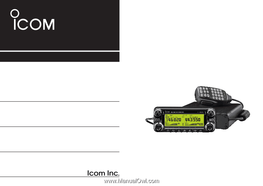
INSTRUCTION MANUAL
i2820H
DUAL BAND FM TRANSCEIVER
This device complies with Part 15 of the FCC Rules. Operation is sub-
ject to the following two conditions: (1) this device may not cause
harmful interference, and (2) this device must accept any interference
received, including interference that may cause undesired operation.