Icom IC-2820H Instruction Manual - Page 30
Main unit - software
 |
View all Icom IC-2820H manuals
Add to My Manuals
Save this manual to your list of manuals |
Page 30 highlights
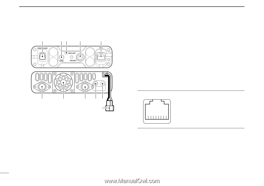
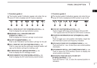
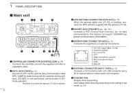
1 PANEL DESCRIPTION ■ Main unit q we r t y u i o !0 !1 q CONTROLLER CONNECTOR [CONTROLLER] (p. III) Connects the controller unit with the supplied controller or separation cable. w DATA JACK [DATA] (p. 57) Connect to a PC via the optional data communication cable OPC-1529R for data cloning with the optional cloning software, CS-2820, or low-speed data communication in DV* mode operation. *Available only when the optional UT-123 is installed. 9 e GPS ANTENNA CONNECTOR [GPS ANT] (p. IV) When the optional digital unit, UT-123, is installed, connects the GPS antenna supplied with the optional UT-123. r PACKET JACK [PACKET] (pgs. 120, 121) Connects a TNC (Terminal Node Controller), etc. for data communications. The receiver can support 1200/9600 bps packet communication (AFSK/GMSK). t MICROPHONE CONNECTOR [MIC] (p. IV) Connects the supplied or an optional microphone. q +8 V DC output (Max. 10 mA) w Channel up/down e 8 V control IN r PTT i q t GND (microphone ground) y MIC (microphone input) u GND i Data IN y ANTENNA CONNECTOR [ANT1 TX/RX] (p. IX) Connects a 50 Ω antenna with a PL-259 connector and a 50 Ω coaxial cable for transmission and reception. u COOLING FAN Rotates while transmitting. Also rotates while receiving depending on the setting in set mode. (p. 101)
-
 1
1 -
2
-
3
-
4
-
5
-
6
-
7
-
8
-
9
-
10
-
11
-
12
-
13
-
14
-
15
-
16
-
17
-
18
-
19
-
20
-
21
-
22
-
23
-
24
-
 25
25 -
 26
26 -
 27
27 -
 28
28 -
 29
29 -
 30
30 -
 31
31 -
 32
32 -
 33
33 -
 34
34 -
 35
35 -
36
-
37
-
38
-
39
-
40
-
41
-
42
-
43
-
44
-
45
-
46
-
47
-
48
-
49
-
50
-
51
-
52
-
53
-
54
-
55
-
56
-
57
-
58
-
59
-
60
-
61
-
62
-
63
-
64
-
65
-
66
-
67
-
68
-
69
-
70
-
71
-
72
-
73
-
74
-
75
-
76
-
77
-
78
-
79
-
80
-
81
-
82
-
83
-
84
-
85
-
86
-
87
-
88
-
89
-
90
-
91
-
92
-
93
-
94
-
95
-
96
-
97
-
98
-
99
-
100
-
101
-
102
-
103
-
104
-
105
-
106
-
107
-
108
-
109
-
110
-
111
-
112
-
113
-
114
-
115
-
116
-
117
-
118
-
119
-
120
-
121
-
122
-
123
-
124
-
125
-
126
-
127
-
128
-
129
-
130
-
131
-
132
-
133
-
134
-
135
-
136
-
137
-
138
-
139
-
140
-
141
-
142
-
143
-
144
-
145
-
146
-
147
-
148
-
149
-
150
-
151
-
152
-
153
-
154
-
155
-
156
-
157
-
158
-
159
-
160
-
161
-
162
-
163
-
164
 |
 |