Icom IC-2820H Instruction Manual - Page 143
Adjusting the transmit signal output from, the TNC, Packet operation band selection
 |
View all Icom IC-2820H manuals
Add to My Manuals
Save this manual to your list of manuals |
Page 143 highlights
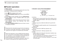
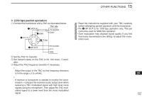
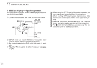
OTHER FUNCTIONS 15 D Adjusting the transmit signal output from the TNC When setting data transmission speed to 9600 bps, the data signal coming from the TNC is applied exclusively to the internal limiter circuitry to automatically maintain band width. NEVER apply data levels from the TNC of over 0.6 V p-p, otherwise the transceiver will not be able to maintain the band width and may possibly interfere with other stations. 1. When using a level meter or oscilloscope, adjust the TX audio output level (DATA IN level) from the TNC as follows. 0.4 V p-p (0.2 V rms) : recommended level 0.2 V p-p-0.5 V p-p (0.1-0.25 V rms) : acceptable level 2. When NOT using a measuring device. q Connect the transceiver to a TNC. w Enter a test mode ("CALL", etc.) on the TNC, then transmit some test data. e When the transceiver fails to transmit the test data or transmits sporadically (TX indicator doesn't appear or flashes): - Decrease the TNC output level until the transmit indicator lights continuously. When transmission is not successful even though the TX indicator lights continuously: - Increase the TNC output level. D Packet operation band selection 1 Both bands, or either the left or right band only, can be spec- ified for packet operation to suit your preference. 2 q Push [F• ] to display function guide. 3 w Push [MENU](V/MHz•SCAN) (Right band's) to enter MENU 4 screen. e Rotate [DIAL] to select "PACKET" then push 5 [MAIN•BAND]. 6 r Rotate [DIAL] to select "PACKET BAND" then push [MAIN•BAND]. 7 t Rotate [DIAL] to select desired band from MAIN (default), 8 left (L) and right (R), then push [MAIN•BAND]. • MAIN : The main band is used for packet op- 9 eration. 10 • Left (L)/Right (r) : The selected left or right band can only be used for packet operation. 11 y Push [BACK](V/MHz•SCAN) (Right band's) twice to return 12 to frequency indication. 13 14 15 16 17 18 19 122
-
 1
1 -
2
-
3
-
4
-
5
-
6
-
7
-
8
-
9
-
10
-
11
-
12
-
13
-
14
-
15
-
16
-
17
-
18
-
19
-
20
-
21
-
22
-
23
-
24
-
25
-
26
-
27
-
28
-
29
-
30
-
31
-
32
-
33
-
34
-
35
-
36
-
37
-
38
-
39
-
40
-
41
-
42
-
43
-
44
-
45
-
46
-
47
-
48
-
49
-
50
-
51
-
52
-
53
-
54
-
55
-
56
-
57
-
58
-
59
-
60
-
61
-
62
-
63
-
64
-
65
-
66
-
67
-
68
-
69
-
70
-
71
-
72
-
73
-
74
-
75
-
76
-
77
-
78
-
79
-
80
-
81
-
82
-
83
-
84
-
85
-
86
-
87
-
88
-
89
-
90
-
91
-
92
-
93
-
94
-
95
-
96
-
97
-
98
-
99
-
100
-
101
-
102
-
103
-
104
-
105
-
106
-
107
-
108
-
109
-
110
-
111
-
112
-
113
-
114
-
115
-
116
-
117
-
118
-
119
-
120
-
121
-
122
-
123
-
124
-
125
-
126
-
127
-
128
-
129
-
130
-
131
-
132
-
133
-
134
-
135
-
136
-
137
-
 138
138 -
 139
139 -
 140
140 -
 141
141 -
 142
142 -
 143
143 -
 144
144 -
 145
145 -
 146
146 -
 147
147 -
 148
148 -
149
-
150
-
151
-
152
-
153
-
154
-
155
-
156
-
157
-
158
-
159
-
160
-
161
-
162
-
163
-
164
 |
 |