Icom IC-2820H Instruction Manual - Page 24
Function display
 |
View all Icom IC-2820H manuals
Add to My Manuals
Save this manual to your list of manuals |
Page 24 highlights
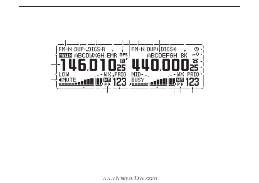
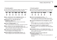
1 PANEL DESCRIPTION ■ Function display q we r t y qu q w e r i o @2 !0 !1 !2 !2 !9 !3 @1 !8 !7 !6 !5!3 !4 @0 !9 !8 !7 !6 !5 !4 *The same indications for both the left and right bands are arranged. q OPERATING MODE INDICATOR (p. 21) Shows the selected operating mode. • FM, FM-N, AM, AM-N and DV* are available, depending on operating band. *Available only when the optional UT-123 is installed. w DUPLEX INDICATORS (p. 30) "DUP+" appears when plus duplex, "DUP -" appears when minus duplex (repeater) operation is selected. e NAME INDICATOR During memory mode operation, the programmed memory or memory bank name is displayed. r TONE INDICATOR ➥ During FM mode operation: ● "TONE" appears while the repeater tone is in use. (p. 30) ● "TSQL" appears while the tone squelch function is in use. (p. 86) ● "TSQL-R" appears while the reverse tone squelch function is in use. (p. 87) ● "DTCS" appears while the DTCS squelch function is in use. (p. 86) ● "DTCS-R" appears while the reverse DTCS squelch function is in use. (p. 87) 3
-
 1
1 -
2
-
3
-
4
-
5
-
6
-
7
-
8
-
9
-
10
-
11
-
12
-
13
-
14
-
15
-
16
-
17
-
18
-
 19
19 -
 20
20 -
 21
21 -
 22
22 -
 23
23 -
 24
24 -
 25
25 -
 26
26 -
 27
27 -
 28
28 -
 29
29 -
30
-
31
-
32
-
33
-
34
-
35
-
36
-
37
-
38
-
39
-
40
-
41
-
42
-
43
-
44
-
45
-
46
-
47
-
48
-
49
-
50
-
51
-
52
-
53
-
54
-
55
-
56
-
57
-
58
-
59
-
60
-
61
-
62
-
63
-
64
-
65
-
66
-
67
-
68
-
69
-
70
-
71
-
72
-
73
-
74
-
75
-
76
-
77
-
78
-
79
-
80
-
81
-
82
-
83
-
84
-
85
-
86
-
87
-
88
-
89
-
90
-
91
-
92
-
93
-
94
-
95
-
96
-
97
-
98
-
99
-
100
-
101
-
102
-
103
-
104
-
105
-
106
-
107
-
108
-
109
-
110
-
111
-
112
-
113
-
114
-
115
-
116
-
117
-
118
-
119
-
120
-
121
-
122
-
123
-
124
-
125
-
126
-
127
-
128
-
129
-
130
-
131
-
132
-
133
-
134
-
135
-
136
-
137
-
138
-
139
-
140
-
141
-
142
-
143
-
144
-
145
-
146
-
147
-
148
-
149
-
150
-
151
-
152
-
153
-
154
-
155
-
156
-
157
-
158
-
159
-
160
-
161
-
162
-
163
-
164
 |
 |