Icom IC-2820H Instruction Manual - Page 25
Shows the selected bank initial.
 |
View all Icom IC-2820H manuals
Add to My Manuals
Save this manual to your list of manuals |
Page 25 highlights
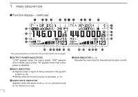
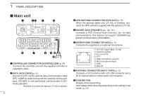
PANEL DESCRIPTION 1 ➥ During DV* (Digital) mode operation: ● "DSQL" appears while the digital call sign squelch function is in use. (p. 91) ● "CSQL" appears while the digital code squelch function is in use. (p. 91) ➥ " " appears with the "TSQL," "DTCS," "DSQL"* or "C SQL"* indicator while the pocket beep function is in use. (pgs. 86, 91) *Available only when the optional UT-123 is installed. t EMR MODE INDICATOR (p. 56) Appears when the EMR mode* operation is in use. *Available only when the optional UT-123 is installed. y GPS INDICATOR (p. 126) Appears while GPS function* is in use. *Available only when the optional UT-123 is installed. u SUB BAND REMOTE CONTROL INDICATOR (p. 96) Appears when the sub band remote control function is in use. i BREAK-IN INDICATOR (p. 51) Appears when the break-in* operation is in use. *Available only when the optional UT-123 is installed. o AUTO POWER OFF INDICATOR (p. 118) Appears when the auto power OFF function is in use. !0 KEY LOCK INDICATOR (p. 19) Appears when the key lock function is activated. !1 DTMF INDICATOR (p. 83) 1 Appears while automatic DTMF transmission is in use. 2 !2 FREQUENCY READOUT Shows the operating frequency, set mode contents, etc. 3 • Frequency decimal point blinks while scanning. (p. 75) 4 !3 PRIORITY INDICATOR (p. 81) Appears while priority watch is activated, blinks while pri- 5 ority watch is paused. 6 !4 MEMORY CHANNEL NUMBER INDICATORS 7 ➥ Shows the selected memory channel number. (p. 61) ➥ Shows the selected bank initial. (p. 64) 8 ➥ "C" appears when the call channel is selected. (p. 72) 9 !5 SKIP INDICATOR (p. 79) 10 ➥ "≈" appears when the displayed memory channel is specified as a skip channel. 11 ➥ "P≈" appears when the displayed frequency is specified 12 as a program skip frequency. 13 !6 MEMORY INDICATOR (p. 61) Appears when memory mode is selected. 14 !7 WEATHER ALERT INDICATOR (p. 123) 15 "WX" appears when the weather alert function is in use. *Available with the USA version only. 16 !8 S/RF INDICATORS 17 ➥ Shows the relative signal strength while receiving sig- 18 nals. (p. 20) ➥ Shows the output power level while transmitting. (p. 21) 19 4
-
 1
1 -
2
-
3
-
4
-
5
-
6
-
7
-
8
-
9
-
10
-
11
-
12
-
13
-
14
-
15
-
16
-
17
-
18
-
19
-
 20
20 -
 21
21 -
 22
22 -
 23
23 -
 24
24 -
 25
25 -
 26
26 -
 27
27 -
 28
28 -
 29
29 -
 30
30 -
31
-
32
-
33
-
34
-
35
-
36
-
37
-
38
-
39
-
40
-
41
-
42
-
43
-
44
-
45
-
46
-
47
-
48
-
49
-
50
-
51
-
52
-
53
-
54
-
55
-
56
-
57
-
58
-
59
-
60
-
61
-
62
-
63
-
64
-
65
-
66
-
67
-
68
-
69
-
70
-
71
-
72
-
73
-
74
-
75
-
76
-
77
-
78
-
79
-
80
-
81
-
82
-
83
-
84
-
85
-
86
-
87
-
88
-
89
-
90
-
91
-
92
-
93
-
94
-
95
-
96
-
97
-
98
-
99
-
100
-
101
-
102
-
103
-
104
-
105
-
106
-
107
-
108
-
109
-
110
-
111
-
112
-
113
-
114
-
115
-
116
-
117
-
118
-
119
-
120
-
121
-
122
-
123
-
124
-
125
-
126
-
127
-
128
-
129
-
130
-
131
-
132
-
133
-
134
-
135
-
136
-
137
-
138
-
139
-
140
-
141
-
142
-
143
-
144
-
145
-
146
-
147
-
148
-
149
-
150
-
151
-
152
-
153
-
154
-
155
-
156
-
157
-
158
-
159
-
160
-
161
-
162
-
163
-
164
 |
 |