Netgear WC7520 WC7520 Reference Manual - Page 11
Rear Panel Features, Table 1., LED Functions Continued - default password
 |
UPC - 606449072969
View all Netgear WC7520 manuals
Add to My Manuals
Save this manual to your list of manuals |
Page 11 highlights
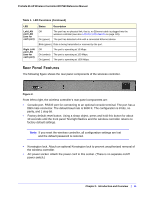
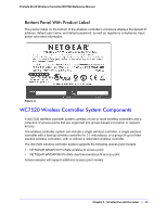
ProSafe 20-AP Wireless Controller WC7520 Reference Manual Table 1. LED Functions (Continued) LED Left LAN port LED (one for each port) Right LAN port LED (one for each port) Status Description Off The port has no physical link, that is, no Ethernet cable is plugged into the wireless controller (see also LAN Port LEDs Not On on page 145). On (green) The port has detected a link with a connected Ethernet device. Blink (green) Data is being transmitted or received by the port. Off The port is operating at 10 Mbps. On (amber) The port is operating at 100 Mbps. On (green) The port is operating at 1000 Mbps. Rear Panel Features The following figure shows the rear panel components of the wireless controller. Figure 2. From left to right, the wireless controller's rear panel components are: • Console port. RS232 port for connecting to an optional console terminal. The port has a DB9 male connector. The default baud rate is 9600 K. The configuration is 8 bits, no parity, and 1 stop bit. • Factory default reset button. Using a sharp object, press and hold this button for about 10 seconds until the front panel Test light flashes and the wireless controller returns to factory default settings. Note: If you reset the wireless controller, all configuration settings are lost and the default password is restored. • Kensington lock. Attach an optional Kensington lock to prevent unauthorized removal of the wireless controller. • AC power socket. Attach the power cord to this socket. (There is no separate on/off power switch.) Chapter 1: Introduction and Overview | 11
-
 1
1 -
2
-
3
-
4
-
5
-
 6
6 -
 7
7 -
 8
8 -
 9
9 -
 10
10 -
 11
11 -
 12
12 -
 13
13 -
 14
14 -
 15
15 -
 16
16 -
17
-
18
-
19
-
20
-
21
-
22
-
23
-
24
-
25
-
26
-
27
-
28
-
29
-
30
-
31
-
32
-
33
-
34
-
35
-
36
-
37
-
38
-
39
-
40
-
41
-
42
-
43
-
44
-
45
-
46
-
47
-
48
-
49
-
50
-
51
-
52
-
53
-
54
-
55
-
56
-
57
-
58
-
59
-
60
-
61
-
62
-
63
-
64
-
65
-
66
-
67
-
68
-
69
-
70
-
71
-
72
-
73
-
74
-
75
-
76
-
77
-
78
-
79
-
80
-
81
-
82
-
83
-
84
-
85
-
86
-
87
-
88
-
89
-
90
-
91
-
92
-
93
-
94
-
95
-
96
-
97
-
98
-
99
-
100
-
101
-
102
-
103
-
104
-
105
-
106
-
107
-
108
-
109
-
110
-
111
-
112
-
113
-
114
-
115
-
116
-
117
-
118
-
119
-
120
-
121
-
122
-
123
-
124
-
125
-
126
-
127
-
128
-
129
-
130
-
131
-
132
-
133
-
134
-
135
-
136
-
137
-
138
-
139
-
140
-
141
-
142
-
143
-
144
-
145
-
146
-
147
-
148
-
149
-
150
-
151
-
152
-
153
-
154
-
155
-
156
-
157
-
158
-
159
-
160
-
161
-
162
 |
 |
